Photovoltaic microstorage microinverter

a micro-inverter and photovoltaic technology, applied in the direction of dc-ac conversion without reversal, emergency power supply arrangement, transportation and packaging, etc., can solve the problems of inconvenient operation, and inefficient control of pv power collection by string inverter. achieve the effect of reducing costs and better control of pv power

Inactive Publication Date: 2017-07-13
PV MICROSTORAGE LLC
View PDF0 Cites 12 Cited by
  • Summary
  • Abstract
  • Description
  • Claims
  • Application Information

AI Technical Summary

Benefits of technology

[0013]There exists a need for a PV system that provides scalable and distributed power control and storage on a per-PV-panel basis. Therefore, th...

Problems solved by technology

This technique is extremely inefficient because of the variances in the power generation of all the PV panels and the inability for a string inverter to control the individual PV panels.
For instance, different panels in the same string can be generating a wide variance of power due to dynamic shadowing, but using a string inverter thus inefficiently controls the PV power collection.
Such multiple PV panel arrays, if equipped with energy storage, will have large batteries, which can also be cost prohibitive.
Problems also arise in the scalability of these systems.
In these systems, the grid connection is necessary because no extant string inverter can power even a small building.
In addition, these systems do not scale; it is difficult to add additional or more efficient PV panels to a string after the string inverter is installed.
Such systems are very complex, requiring a battery charger, a PV inverter, a battery inverter, and a sub-panel.
Extant battery inverters can power only moderate loads, thus requiring either a sub-panel in addition to the building service panel or that the building be very small.
In addition, these extant microinverters cannot operate off-grid.
Some techniques have been developed to improve PV power collection and control, but those techniques continue to fail to address per-PV-panel granularity to maximize power collection, distribution, efficiency, storage, and scalability.
While Wolter provides the external master controller, this external master controller still operates a single control unit for...

Method used


Image

  • Photovoltaic microstorage microinverter
  • Photovoltaic microstorage microinverter
  • Photovoltaic microstorage microinverter

Examples


Embodiment Construction

[0023]The present PV electric system overcomes the deficiencies of the prior art in providing a per-PV-panel solution for controlling and distributing PV power. The present PV system further improves system efficiency and control through the controller algorithms, scalability, and distributed energy storage.

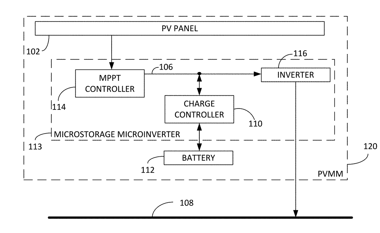
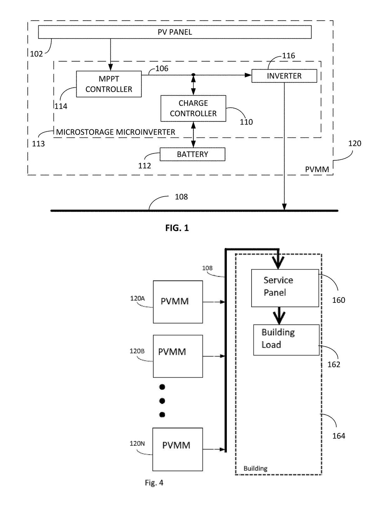
[0024]FIG. 1 illustrates the present invention of a PV electric system 120. The system of FIG. 1 includes the PV panel 102, the MPPT controller 114, the charge controller 110, the battery 112, the DC bus 106, and the inverter 116, as well as the AC bus 108. The system 120 is one embodiment of a photovoltaic microstorage microinverter (PVMM). Furthermore, as referred herein, the MPPT controller 114, the charge controller 110, the DC bus 106 and the inverter 116 collectively make up the microstorage microinverter 113.

[0025]It is recognized by one skilled in the art that further elements and connectivity means may be utilized and incorporated into the present system, whereby these m...


PUM


Abstract

A PV electrical system includes a PV panel, a MPPT controller, a charge controller coupled to a battery and an inverter generating alternating current output based on a first charge controller output disposed within the PV panel. The system further includes an AC bus receiving the alternating current output, whereby any number of PV panels are connected to the AC bus for providing power output. In varying embodiments, the connectivity of the components provides for charging and controlling output of the battery, as well as managing power distribution across the AC bus, on a per-panel basis.

Description

COPYRIGHT NOTICE[0001]A portion of the disclosure of this patent document contains material, which is subject to copyright protection. The copyright owner has no objection to the facsimile reproduction by anyone of the patent document or the patent disclosure, as it appears in the Patent and Trademark Office patent files or records, but otherwise reserves all copyright rights whatsoever.FIELD OF INVENTION[0002]The disclosed technology relates generally to photovoltaic (PV) panels and more specifically to the inclusion of PV-panel-specific components for controlling distributed, scalable PV power generation and storage.BACKGROUND[0003]Advancements in PV technology have been focused on harnessing power generated from the PV panels, overlooking techniques for fine-tuning the control and storage of distributed, scalable PV power.[0004]For instance, common technologies for PV power provide for multiple PV panels connected in a series string and then a single string inverter unit controll...

Claims


Application Information

Patent Timeline
IPC IPC(8): H02J3/38H02J7/35H02M7/44H02J7/00
CPCH02J3/383H02J7/0068H02M7/44H02J7/35H02J7/007H02J9/062H02J2310/10H02J2300/26H02J3/381Y02B10/10Y02B10/70Y02E10/56
Inventor CARPENTER, P. KEVIN
Owner PV MICROSTORAGE LLC
Why Eureka
Try Eureka