Power conversion device and refrigeration cycle apparatus

a technology of power conversion device and refrigeration cycle, which is applied in the direction of refrigeration components, mechanical energy handling, light and heating apparatus, etc., can solve the problems of increasing the current of the compressor, and reducing so as to reduce the carrier frequency, improve the efficiency of the converter, and reduce the loss caused by switching

Active Publication Date: 2017-07-13
MITSUBISHI ELECTRIC CORP
View PDF4 Cites 8 Cited by
  • Summary
  • Abstract
  • Description
  • Claims
  • Application Information

AI Technical Summary

Benefits of technology

[0012]According to the present invention, by adopting the booster circuit composed of the above configuration, it is made possible to decrease the carrier frequency without increasing a ripple current flowing through the reactor, and it is made possible to decrease loss caused by switching. Thus, switching loss is improved. In addition, since the ripple curr

Problems solved by technology

In such a case, when the motor is caused to be operated in a high-speed range exceeding this rotation speed (e.g., during high-load operation), since the inverter device cannot output a voltage equal to or higher than the power supply voltage, the current of the compressor increases due to output voltage saturation, and the efficiency of a conver

Method used


Image

  • Power conversion device and refrigeration cycle apparatus
  • Power conversion device and refrigeration cycle apparatus
  • Power conversion device and refrigeration cycle apparatus

Examples


embodiment 1

[0023](Configuration of Power Conversion Device)

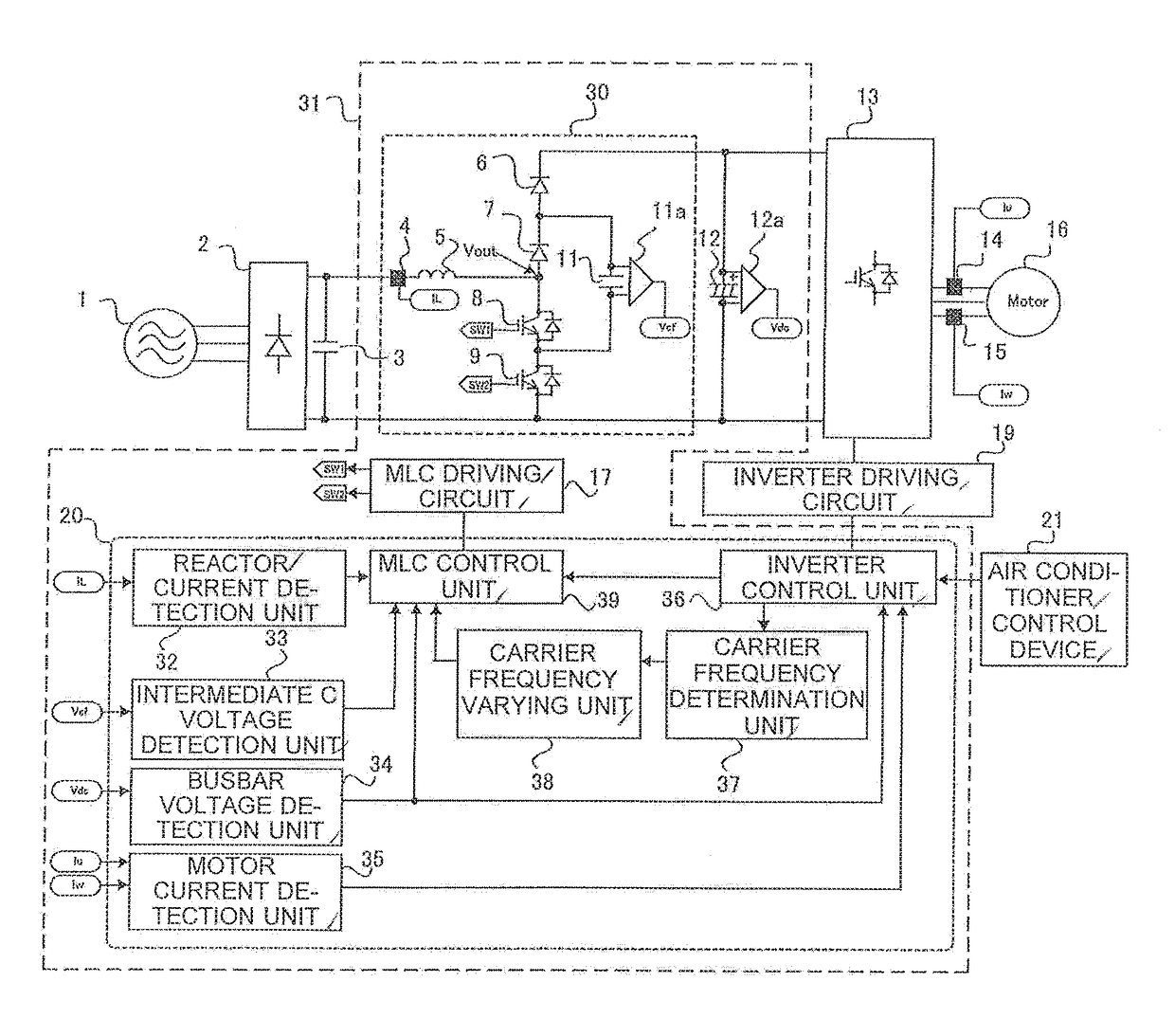
[0024]Hereinafter, a power conversion device according to Embodiment 1 of the present invention will be described with reference to the drawings. FIG. 1 is a circuit diagram of the power conversion device power according to Embodiment 1 of the present invention. The configuration of the power conversion device will be described with reference to FIG. 1. The power conversion device in FIG. 1 includes a rectifier 2 as a rectifier circuit, a ripple filter 3, a reactor current sensor 4, a reactor 5, a first backflow prevention diode 6, a second backflow prevention diode 7, a first switching element 8, a second switching element 9, an intermediate capacitor 11, a voltage sensor 11a, a smoothing capacitor 12, a voltage sensor 12a, an inverter circuit 13, motor current sensors 14 and 15, an MLC driving circuit 17, an inverter driving circuit 19, a controller 20, and an air conditioner control device 21. The rectifier 2 converts an AC voltage ...

embodiment 2

[0053]Regarding a power conversion device according to Embodiment 2 of the present invention, the difference from the power conversion device according to Embodiment 1 will be mainly described.

[0054](Configuration of Power Conversion Device)

[0055]FIG. 7 is a configuration diagram of the power conversion device according to Embodiment 2 of the present invention. FIG. 8 is a diagram showing a relationship among a boost ratio, a ripple current, and a carrier frequency of the power conversion device in FIG. 7. The carrier frequency determination unit 37 in Embodiment 2 determines a carrier frequency on the basis of a condition obtained from the MLC control unit 39. The relationship among the carrier frequency, the ripple current ΔI, and the boost ratio in MLC is a relationship as shown in FIG. 8. Here, the boost ratio is a ratio between a voltage output by the rectifier 2 and a voltage after boosting. It is found that the ripple current decreases as the carrier frequency increases, and ...

embodiment 3

[0059]In Embodiment 3, an example where the power conversion device according to Embodiment 1 or Embodiment 2 is applied to a compressor 51 of an air conditioner will be described.

[0060](Configuration and Operation of Air Conditioner)

[0061]FIG. 9 is a configuration diagram of an air conditioner according to Embodiment 3 of the present invention. Hereinafter, the case where the power conversion device according to Embodiment 1 or Embodiment 2 is applied to the compressor 51 of the air conditioner will be described with reference to FIG. 9.

[0062]A power conversion device 101 shown in FIG. 9 is the power conversion device according to Embodiment 1 or Embodiment 2, and is configured to be supplied with power from an AC power supply 1 and supply the power to the motor 16 to rotationally drive the motor 16. The motor 16 is connected to a compression element 51a, and the motor 16 and the compression element 51a form the compressor 51 which compresses refrigerant.

[0063]A refrigeration cycle...


PUM


Abstract

A rectifier, a booster circuit configured to boost an output voltage of the rectifier, a smoothing capacitor configured to smooth an output voltage of the booster circuit, and an inverter circuit configured to convert a DC voltage of the smoothing capacitor to an AC voltage and drive a motor forming a part of a device supplied with the voltage after the conversion, are included. In addition, a reactor, a first backflow prevention element, a second backflow prevention element, a first switching element, a second switching element, an intermediate capacitor, and a controller configured to control the first switching element and the second switching element, are included.

Description

TECHNICAL FIELD[0001]The present invention relates to a power conversion device and a refrigeration cycle apparatus, such as a refrigeration air-conditioning apparatus, using the power conversion device.BACKGROUND ART[0002]In a large-capacity inverter device that drives a motor for a compressor and a fan, etc. of a refrigeration air-conditioning apparatus, a method is used in which a DC busbar voltage for inverter driving is generated by a three-phase full-wave rectifier circuit. In the refrigeration air-conditioning apparatus, in order to increase energy consumption efficiency (COP) during rated cooling and heating operations and full-year energy consumption efficiency (APF) through one year, the motor for the compressor tends to be designed such that an induced voltage (counter-electromotive force) is substantially equal to a power supply voltage at approximately a rotation speed used in rated operation of the refrigeration air-conditioning apparatus. In such a case, when the moto...

Claims


Application Information

Patent Timeline
IPC IPC(8): H02M5/458H02M1/08F25B31/02H02K7/14H02P6/10H02M1/32H02P27/08
CPCF25B2600/021H02M5/458H02M1/32F25B31/02H02P27/08H02K7/14H02P6/10H02M1/08H02M1/14H02M3/158H02M1/0054H02M7/4837Y02B70/10H02M3/155H02M5/45H02M1/0067
Inventor YUASA, KENTAKUSUBE, SHINSAKUTSUMURA, AKIHIROIWATA, AKIHIKO
Owner MITSUBISHI ELECTRIC CORP
Why Eureka
Try Eureka