Ideal switch bridgeless pfc
- Summary
- Abstract
- Description
- Claims
- Application Information
AI Technical Summary
Benefits of technology
Problems solved by technology
Method used
Image
Examples
Embodiment Construction
Ideal Switch Topologies
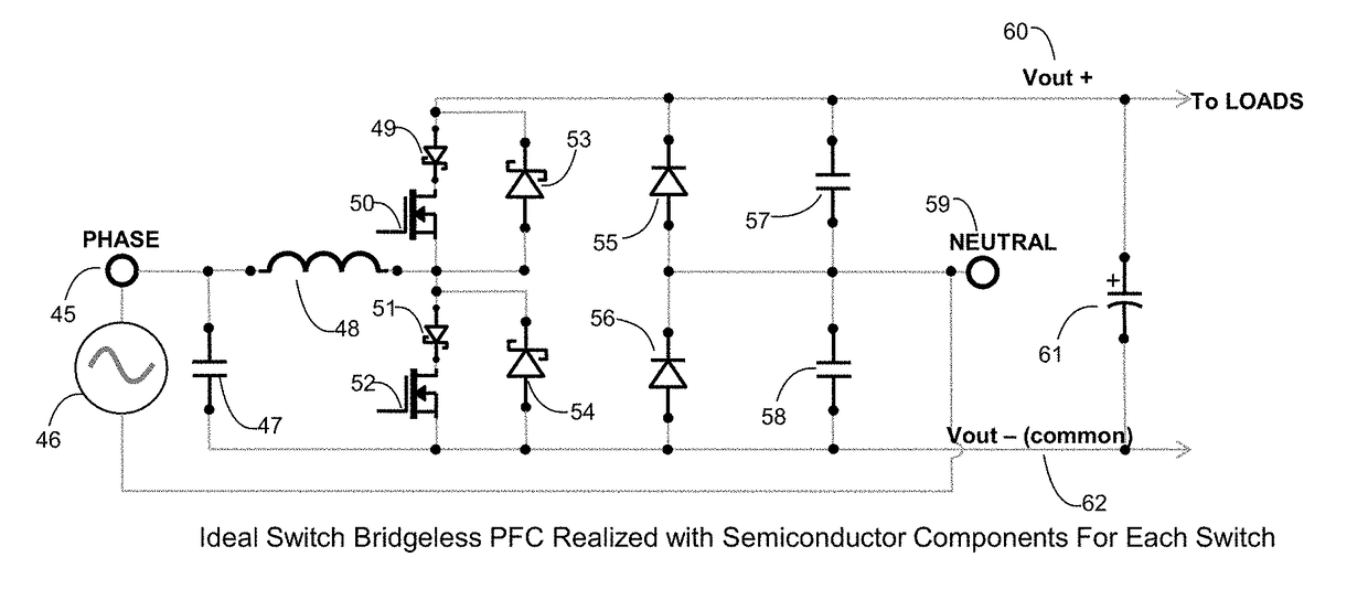
[0051]FIG. 3, shows a topology where the left side of the bridge is replaced by switches (34) and (35). The neutral is held steady compared to common on the right side by the use of two capacitors (38) and (39). Capacitor (32) also can be used for this. A capacitor from phase to Vout can also be used (not shown). In this topology the switches must do the work of both boost switch and diode depending on the polarity of the input line. The drop during an on and off will be a switch and a low frequency diode. Unfortunately most modern day switches cannot fulfill both roles at the same time if the converter is run in continuous conduction mode. Reverse recovery losses in the body diode of the switch fulfilling the diode role would overwhelm the efficiency savings. Even though this topology has the best semiconductor drops it must be modified in order to use silicon MOSFETs due to this problem. Shown in FIG. 4, is a modification where the top switch (35) and bottom...
PUM
 Abstract
Description
Claims
Application Information
 - R&D
- Intellectual Property
- Life Sciences
- Materials
- Tech Scout
- Unparalleled Data Quality
- Higher Quality Content
- 60% Fewer Hallucinations
Browse by: Latest US Patents, China's latest patents, Technical Efficacy Thesaurus, Application Domain, Technology Topic, Popular Technical Reports.
© 2025 PatSnap. All rights reserved.Legal|Privacy policy|Modern Slavery Act Transparency Statement|Sitemap|About US| Contact US: help@patsnap.com


