
Photovoltaic module comprising a polymer front face

a photovoltaic module and polymer technology, applied in the field of photovoltaic modules, can solve the problems of incompatibility of the presence of glass plates in the front face of the photovoltaic module with some applications, inability to achieve the effect of achieving a high module weight and limited integration capacity

Inactive Publication Date: 2017-08-03
COMMISSARIAT A LENERGIE ATOMIQUE ET AUX ENERGIES ALTERNATIVES +1
View PDF6 Cites 3 Cited by
  • Summary
  • Abstract
  • Description
  • Claims
  • Application Information

AI Technical Summary

Benefits of technology

The patent proposes an alternative solution for designing a photovoltaic module to address its limitations in terms of flexibility, rigidity, lightness, flatness, and resistance to impacts and mechanical loads. The technical effects of the patent text include improving the flexibility and durability of the photovoltaic module for better performance and reliability in various applications.

Problems solved by technology

However, these productions known in prior art of a photovoltaic module are not entirely satisfactory and have several disadvantages for at least some of their applications.
As such, first of all, the presence of a glass plate in order to form the front face of the photovoltaic module is not compatible with some applications of the photovoltaic module which may require a relative lightness and a facility for forming the module.
On the contrary, the designs of prior art that use glass as a front face of the photovoltaic modules imply the obtaining of a high weight of the module and a limited integration capacity.
However, simply substituting glass with a polymer material, in order to obtain a light and flexible photovoltaic module, generally results in increased vulnerability of the module to impacts and to mechanical loads, which is unacceptable for some applications.
In this way, the flexibility of each photovoltaic module can be limited and above all insufficient.
Moreover, this also poses a problem of accentuation of the differential expansion constraints between the various layers of the structure, that can lead to undesirable deformations or delaminations at the interfaces of the structure, as for example at the encapsulating / outer layer interface.
However, the solutions described hereinabove are not entirely satisfactory in terms of flexibility, resistance to impacts and mechanical loads, performance and cost of photovoltaic modules, in particular for constraining applications that stress them substantially in terms of their mechanical resistance.
In particular, the materials used in the carrying out of photovoltaic modules according to prior art are not sufficiently satisfactory to respond to such stresses.

Method used


Image

  • Photovoltaic module comprising a polymer front face
  • Photovoltaic module comprising a polymer front face

Examples


Embodiment Construction

[0015]There is therefore a need to propose an alternative solution for the design of a photovoltaic module in order to respond to at least some of the constraints inherent with applications considered by the use of the photovoltaic module, in particular in order to improve the flexibility, rigidity, lightness, flatness and resistance to impacts and mechanical loads of the photovoltaic module.

[0016]The invention has for purpose to overcome at least partially the needs mentioned hereinabove and the disadvantages relating to the products of prior art.

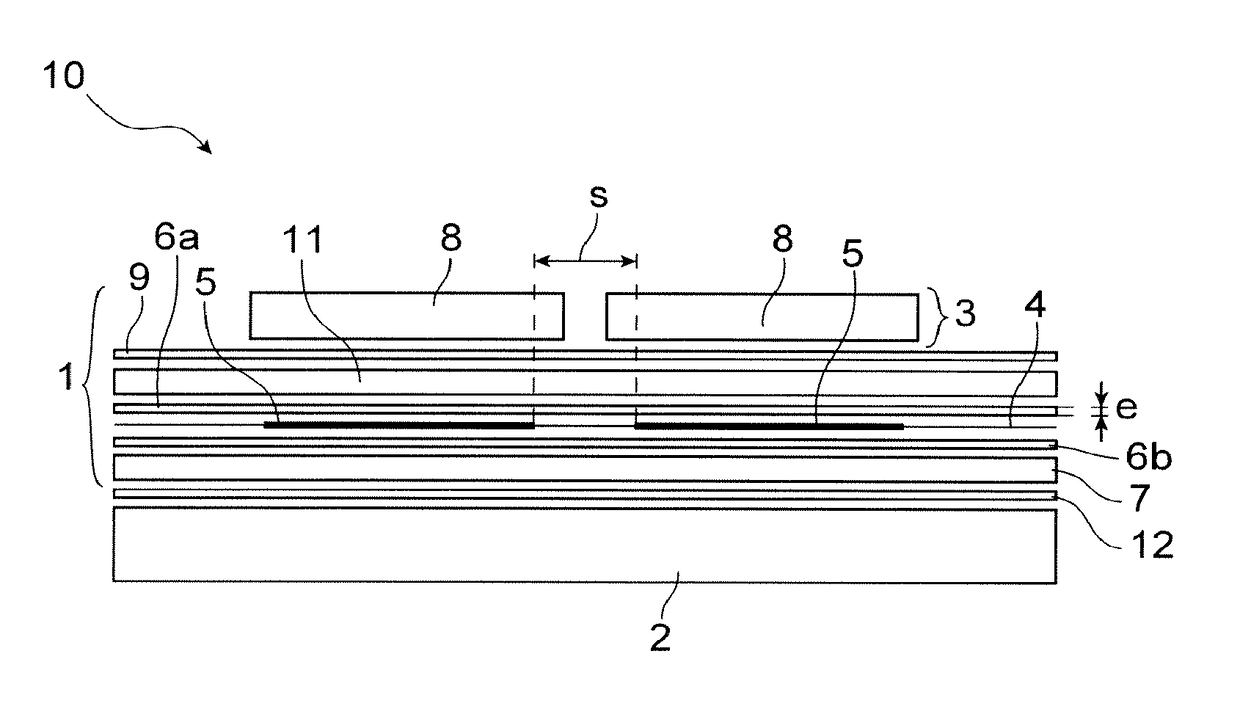
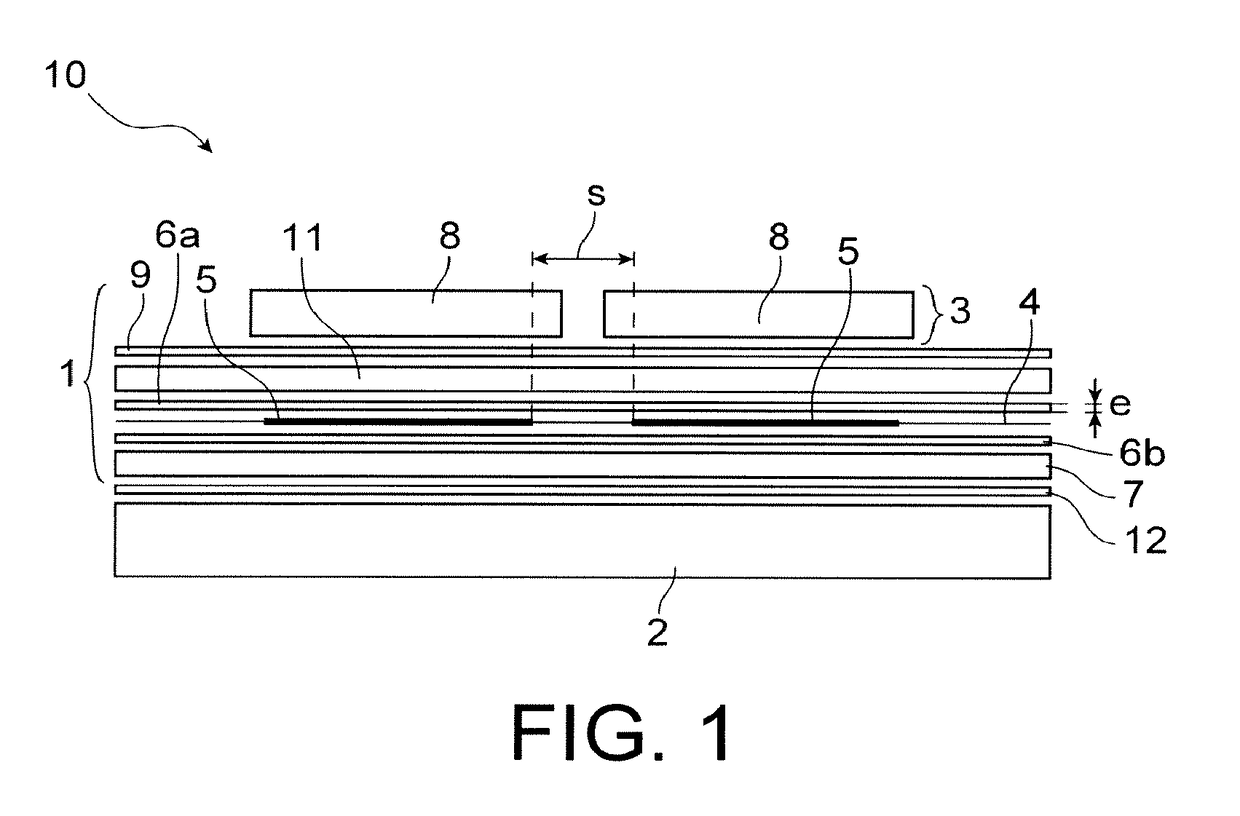
[0017]The invention also has for object, according to one of its aspects, a photovoltaic module comprising at least:[0018]a transparent first layer forming the front face of the photovoltaic module intended to receive a luminous flux,[0019]a set of a plurality of photovoltaic cells arranged side-by-side and connected together electrically,[0020]an assembly encapsulating the plurality of photovoltaic cells,[0021]a second layer forming the r...


PUM


Abstract

A photovoltaic module including a transparent first layer forming a front face, plural photovoltaic cells, and an assembly encapsulating the photovoltaic cells. The first layer includes plural plates independent from each other, each plate located opposite a photovoltaic cell. Rigidity of the encapsulating assembly is defined by a Young's modulus of encapsulation material greater than or equal to 75 MPa at ambient temperature and a thickness of the encapsulating assembly between 0.4 and 1 mm. The first layer includes at least one transparent polymer material of acrylic block copolymers or a composition including at least one acrylic block copolymer having formula (A)nB, in which: n is an integer greater than or equal to 1; A is an acrylic or methacrylic homo- or copolymer having a glass transition temperature greater than 50° C.; and B is an acrylic or methacrylic homo- or copolymer having a glass transition temperature less than 20° C.

Description

TECHNICAL FIELD[0001]This invention relates to the field of photovoltaic modules, comprising a set of photovoltaic cells connected together electrically, and in particular so-called “crystalline” photovoltaic cells, i.e. which have a silicon crystal or silicon polycrystalline base.[0002]The invention can be implemented for many applications, being particularly concerned with applications that require the use of photovoltaic modules that are light, flexible and robust with respect to impacts and high mechanical loads. It can as such in particular be applied for buildings such as residences or industrial premises, for example for the carrying out of the roofs thereof, for the designing of urban furniture, for example for public lighting, road signs or recharging electric cars, or also for the integration thereof in zones where traffic is possible, for pedestrians and / or vehicles, such as road surfaces or roads, bike paths, industrial platforms, squares, pavements, among others.[0003]T...

Claims


Application Information

Patent Timeline
IPC IPC(8): H01L31/048H02S20/20
CPCH01L31/0481H02S20/20H01L31/0488H01L31/048Y02E10/50H01L31/036H01L31/18Y02E10/546
Inventor HIDALGO, MANUELGAUME, JULIENGUILLEREZ, STEPHANESICOT, LIONEL
Owner COMMISSARIAT A LENERGIE ATOMIQUE ET AUX ENERGIES ALTERNATIVES
Learn More