Chemically enhanced oil recovery method using viscosity-increasing polymeric compounds

Active Publication Date: 2017-08-17
SNF SA
View PDF3 Cites 4 Cited by
  • Summary
  • Abstract
  • Description
  • Claims
  • Application Information

AI Technical Summary

Benefits of technology

[0031]The present recovery method allows therefore recycling—at least in part—the viscosity-increasing polymeric compounds previously injected into the oil-bearing formation. Consequently, it allows reducing the amount of new (o

Problems solved by technology

Practical limits are often based on limited water supply.
For some fields, such treatments have been observed to result in an additional 15% to 30% extraction of the OOIP in the formation on top of water flooding.
The treatment of the produced water usually shows to be challenging, particularly considering the high viscosity of the produced water.
Up to now, the techniques for treating the produced waters, obtained from chemically enhanced oil recovery processes, have not shown sufficiently satisfactory.
Particularly, it is not known so far conventional treatment processes for treating t

Method used


Image

  • Chemically enhanced oil recovery method using viscosity-increasing polymeric compounds
  • Chemically enhanced oil recovery method using viscosity-increasing polymeric compounds
  • Chemically enhanced oil recovery method using viscosity-increasing polymeric compounds

Examples


example 1

oncentration Comparison

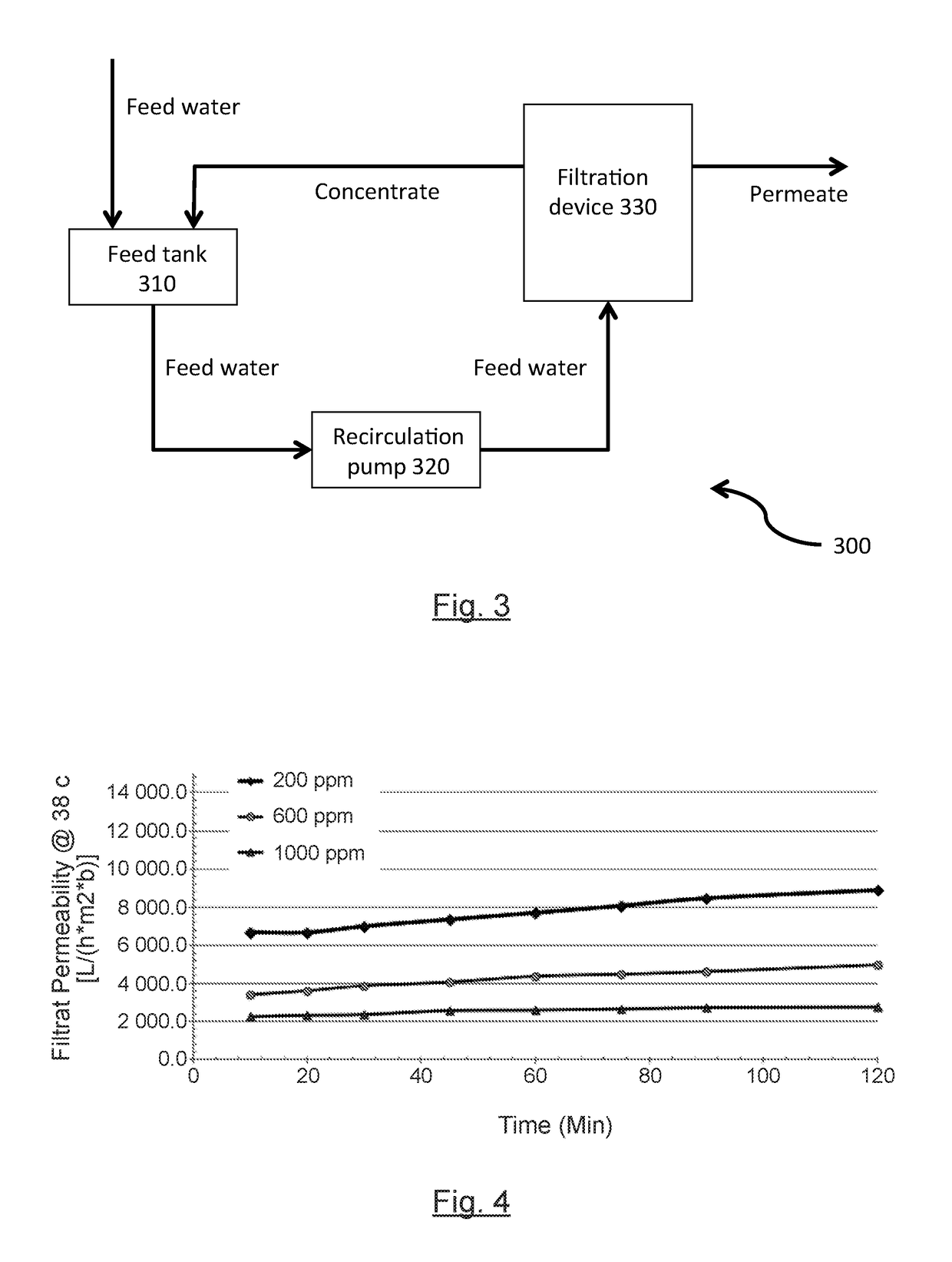
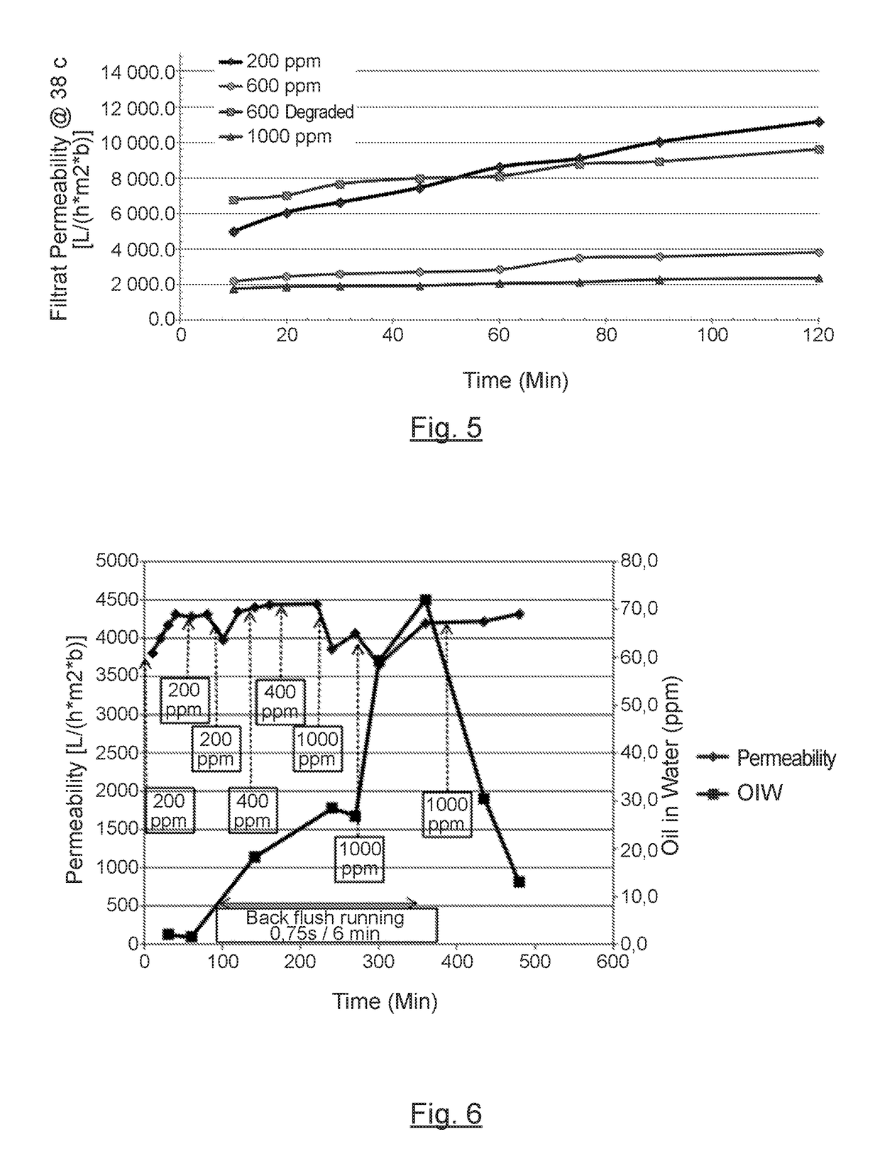
[0145]It has been tested the impact of the concentration of the polymers into the aqueous solution on their permeability through different ceramic membranes.

[0146]The following polymers have been tested:[0147]poly(acrylamide-co-sodium acrylate), with a molecular weight of 7 MDa (herein as “7 MDa polymer”),[0148]poly(acrylamide-co-sodium acrylate), with a molecular weight of 15 MDa (herein as “15 MDa polymer”).

[0149]Four different concentrations of polymer have been tested, namely 200 ppm, 600 ppm, 600 ppm degraded (except for the test of the 7 MDa polymer on the uncoated SiC monolith membrane), and 1000 ppm. When applicable, the polymer is degraded by subjecting it to a high pressure, then dropping the pressure.

[0150]The following ceramic membranes have been tested:[0151]uncoated SiC monolith ceramic membrane, having a membrane cut-off of from about 5 to about 10 μm;[0152]standard TiO2 microfiltration ceramic membrane, having a membrane cut-off of about 0.1 μm...

example 2

tion on Ceramic Membrane (Close Loop)

[0162]It has been tested the efficacy of the permeability of the ceramic membrane, depending on the non-continuous addition of oil.

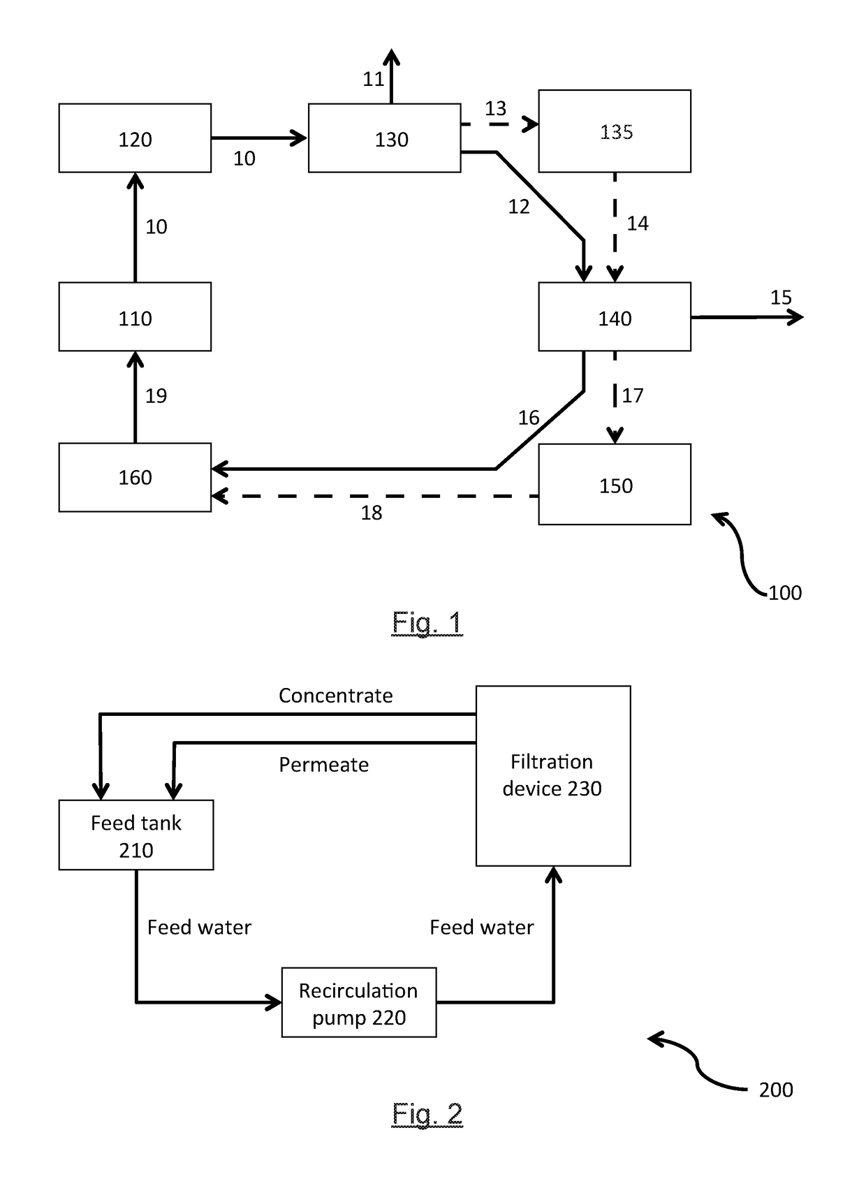
[0163]A schematic representation of the pilot unit is shown on FIG. 2. In the pilot unit 200 shown in FIG. 2, the feed water is directed from the feed tank 210, via a recirculation pump 220, to the filtration device 230, wherein it is subjected to filtration. From this filtration step, it is obtained a permeate stream and a reject stream, which are both fed into the feed tank 210. A transmembrane pressure is applied to the filtration device (not shown).

[0164]The following polymer has been tested:[0165]poly(acrylamide-co-sodium acrylate), with a molecular weight of 7 MDa (herein as “7 MDa polymer”) at a concentration of 600 ppm

[0166]The following ceramic membranes have been tested:[0167]uncoated SiC monolith ceramic membrane, having a membrane cut-off of from about 5 to about 10 μm

[0168]The filtrations have been carrie...

example 3

tion on Ceramic Membrane (Continuous Feed)

[0181]It has been tested the efficacy of the permeability of the ceramic membrane, through a continuous extraction of the permeate and the concentrate.

[0182]A schematic representation of the pilot unit is shown on FIG. 3. In the pilot unit 300 shown in FIG. 3, the feed water is directed to the feed tank 310. The feed water is then continuously directed from the feed tank 310, via a recirculation pump 320, to the filtration device 330, wherein it is subjected to filtration. From this filtration step, it is obtained a permeate stream and a reject stream. The reject stream is directed back from the filtration device to the feed tank 310. A transmembrane pressure is applied to the filtration device (not shown).

[0183]The following compounds have been tested:[0184]7 MDa polymer at a concentration of 600 ppm;[0185]Oil at a concentration of 1000 ppm;[0186]Total Suspended Solids at a concentration of 50 ppm and with a particle size of about 100 μm to...


PUM


Abstract

The present invention is concerned with the treatment of produced water, obtained from a chemically enhanced oil recovery process using viscosity-increasing polymeric compounds. Said treatment comprises particularly the steps of obtaining a produced water, from an oil-water mixture recovered from an oil-bearing formation, wherein the produced water comprises the viscosity-increasing polymeric compounds; and, of directing the produced water to a specific filtration device, and subjecting the produced water to filtration, for obtaining a retentate stream and a permeate stream. Said process allows particularly obtaining a permeate comprising the viscosity-increasing polymeric compounds, said permeate being substantially free of suspended solids, free oil and emulsified oil.

Description

FIELD OF THE INVENTION[0001]The present invention relates to a chemically enhanced oil recovery method, comprising particularly a treatment process using ceramic membranes.BACKGROUND OF THE INVENTION[0002]Significant portions of known oil reserves are bound in formations requiring enhanced oil recovery (EOR) techniques for effective and efficient extraction. Such reserves exist in previously untapped fields as well as in fields where traditional oil recovery has reached a practical limit.[0003]Among EOR techniques are steam-driven recovery methods, and non steam-driven recovery methods. Steam-driven approaches include the Steam-Assisted Gravity Discharge (SAGD) technique. Non steam-driven approaches include for example water flooding and chemical flooding.[0004]Water flooding comprises sweeping oil from oil-bearing formations by injecting large volumes of water into the formations and extracting the resulting oil-water mixture topside for processing. Generally, even after such water...

Claims


Application Information

Patent Timeline
IPC IPC(8): C09K8/588E21B43/40B01D63/06B01D61/14B01D71/02B01D65/02E21B43/16C02F1/44
CPCC09K8/588E21B43/16E21B43/40C02F1/444B01D61/147B01D71/027B01D63/066C02F2101/32B01D2321/04B01D2325/20B01D65/02C02F1/40E21B43/34C02F2103/10C02F2103/365B01D71/024C02F1/68E21B43/35B01D71/025
Inventor HENDOU, MOULOUDSAGNE, CAMILLEFAVERO, CEDRICKGIL, LUDWIGRIVAS, CHRISTOPHE
Owner SNF SA
Why Eureka
Try Eureka