Arrangement in boom system

Active Publication Date: 2017-08-24
PONSSE
View PDF0 Cites 3 Cited by
  • Summary
  • Abstract
  • Description
  • Claims
  • Application Information

AI Technical Summary

Benefits of technology

[0012]This way, an even lighter boom system structure than before is achieved as a whole. This way, it is possible to improve both the performance

Problems solved by technology

However, each weld joint in a boom part or made to it weakens its fatigue resistance and thus shortens the service life and reliable operation of the boom system.
The reverse side of such solutions is, however, that they increase the weight of the boom system, which in turn weakens the perfor

Method used


Image

  • Arrangement in boom system
  • Arrangement in boom system
  • Arrangement in boom system

Examples


Embodiment Construction

[0027]The present figures do not show the arrangement in a boom system in scale but the figures are schematic and illustrate the general structure and operation of the preferred embodiments. The structural parts shown by reference numbers in the attached figures then correspond to the structural parts marked by reference numbers in this specification.

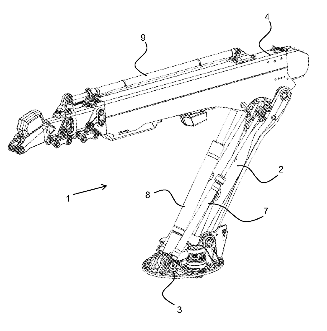
[0028]FIG. 1 shows by way of example a crane with a sliding boom, in which the present arrangement is utilised. This type of boom system 1 formed by the crane comprises at least two boom parts arranged turnably to each other, of which the first boom part 2, i.e. main boom, is conventionally connected to a forest machine by using a turning substructure 3, turning device, or crane table, for instance. In this case, the present arrangement forms the main boom. The second boom part 4 of the figure, i.e. the folding boom with its telescopic extension, is conventionally arranged directly or indirectly to support a tool known per se, such as a...


PUM


Abstract

An arrangement in a boom system, specifically in a forest machine, includes at least two interlinked boom parts and at least one power transmission connected to the boom parts for moving the boom parts in relation to each other and the environment. The boom part includes an elongated body with a hollow structure and at least one set of joints intersected by turning axles for attaching the boom part to an adjacent structure, and at least one set of attachments for attaching an actuator controlling the boom system to the body, whereby at least one boom part is formed as a uniform, hollow piece made of fluid material. The cross-section of the body is made to cinch toward the midpoint of the body.

Description

BACKGROUND OF THE INVENTION[0001]The present invention relates to an arrangement according to claim 1 in a boom system used in a forest machine, in particular. This type of boom system comprises at least two interlinked boom parts and at least one power transmission means connected to the boom parts for moving the boom parts in relation to each other and the environment.[0002]In a forest machine, a boom system is used for controlling various tools, such as a cutting head of a harvester or a timber grabbing bucket of a forwarder. The boom system then comprises two or more interlinked boom parts, the movement of which is controlled by actuators that are connected to lugs or corresponding fastening means attached to the boom parts for this purpose. These fastening means are arranged to transmit the desired force effect or support reaction to the structure of the boom part. In the case of a forest machine, these actuators forming the power transmission means are typically pressure mediu...

Claims


Application Information

Patent Timeline
IPC IPC(8): A01G23/00B66C23/68
CPCB66C23/68A01G23/00B66C23/54B66C23/64
Inventor AUVINEN, TONIHALONEN, MARKO
Owner PONSSE
Why Eureka
Try Eureka