Some disadvantages of traditional methods of
spinal surgery include, for example, the pain associated with the procedure, the length of the procedure, the complexity of implements used to carry out the procedure, the prolonged hospitalization required to manage pain, the
risk of infection due to the invasive nature of the procedure, and the possible requirement of a second procedure to harvest autograft bone from the
iliac crest or other suitable site on the patient for generating the required quantity of cancellous and / or
cortical bone.
Many companies provide various forms of bone graft in varying degrees of liquidity and
viscosity, which may cause problems in certain prior art delivery devices in both prepackaged or packaged by the surgeon embodiments.
However, this procedure requires extra
surgery to remove bone from another area of the patient's body such as the
pelvis or fibula.
Thus, it has been reported that about 30 percent of patients have significant pain and tenderness at the graft harvest site, which may be prolonged, and in some cases outlast the
back pain the procedure intended to correct.
Similarly,
allograft bone and other bone graft substitutes, although eliminating the need for a second
surgery, have drawbacks in that they have yet to be proven as cost effective and efficacious substitutes for
autogenous bone fusion.
However, use of BMPs, although efficacious in promoting
bone growth, can be prohibitively expensive.
This approach also has limitations.
Specifically, surgeons have expressed concerns that
genetically engineered BMPs can dramatically speed the growth of cancerous cells or cause non-cancerous cells to become more sinister.
Another concern is unwanted bone creation.
The traditional devices for inserting bone graft impair the surgeon's
visualization of the operative site, which can lead to imprecise
insertion of bone graft and possible harm to the patient.
The caulking gun and the collection of large
barrel /
plunger designs typically present components at the top of their structure which block the view of the
surgical site.
Such rough maneuvering can result in imprecise placement of bone graft, and in some cases, rupture of the surgical area by penetrating the annulus and entering the
abdominal cavity.
Also, in some
surgical procedures, the devices for inserting bone graft material are applied within a cannula inserted or placed in the surgical area, further limiting the size and / or profile of the bone graft
insertion device.
When a cannula is involved, some traditional devices such as the large
barrel /
plunger designs and / or the chalking gun designs simply cannot be used as they cannot be inserted within the cannula.
Such a delivery method causes the
bone grafting material to become impacted at the bottom of the delivery device, and promotes risk of rupture of the surgical area by penetrating the annulus and entering the
abdominal cavity.
Further, traditional devices that deliver bone graft material along their longitudinal axis may cause rupture of the surgical area or harm to the patient because of the ensuing pressure imparted by the ejected bone graft material from the longitudinal axis of the device.
Mikhail, however, is designed solely for use with
slurry-type bone graft, and does not accommodate bone graft in granule form, which often varies in size among granules and does not have the same “flow” or
viscosity characteristics as
slurry-type bone graft.
Thus, the applicator of Mikhail is insufficient for introducing most bone graft to a
surgical site in a patient.
Like Mikhail, the Thornhill delivery device is designed for use with bone
slurry, and requires much custom
instrumentation and different sized parts to achieve success in many bone graft delivery applications, which in turn increases the time to assemble and use the delivery device and may create further problems during the
surgical operation.
Like the devices of Thornhill and Mikhail, the device disclosed by Smith is clearly designed solely for slurry type bone graft, and does not provide an effective opening for receiving the desired amount of bone graft.
Furthermore, the hollow tube shown by Smith is narrow and does not have a footing or other apparatus associated with the delivery device for preventing the device from penetrating, for example, the abdominal region of a patient, which may occur during tamping or packing of the bone graft.
This in turn may cause serious injury to a patient if not controlled, and for these reasons the device of Smith is also insufficient for delivery of bone graft to a surgical site.
The problems associated with separate administration of the biologic material bone graft material and the
insertion of a fusion cage include applying the graft material in the path of the cage, restricting and limiting the biologic material dispersed within the
disk space, and requiring that the fusion cage be pushed back into the same place that the fusion material delivery device was, which can lead to additional trauma to the delicate nerve structures.
In particular, achieving a complete fusion in the middle portion of the cage has been particularly problematic.
As such, the Perez-Cruet fusion device is unlikely to completely fill the areas near of its fusion cage and deliver bone graft material to the surrounding bone graft site.
Furthermore, none of the Perez-Cruet fusion device embodiments feature a defined
interior space or a cage-style design.
Furthermore, the Perez-Cruet does not feature a distal tip that functions to precisely position the fusion device and stabilize the device during delivery of bone graft material.
The Grotz
system does not allow precise positioning or delivery of bone graft material without an
implant and requires a complex and bulky insertion tool.
Lawson does not allow precise positioning or delivery of viscous bone graft material and has no capability to interconnect or integrate with an
implant such as a bone graft fusion cage.
The Alfaro
system does not allow precise positioning or delivery of bone graft material through a distal tip that precisely positions the fusion device and stabilizes the device during delivery of bone graft material, and does not allow primarily lateral injection of bone graft fusion material.
Moreover, these bone graft delivery devices generally cannot
handle particulate bone graft of varying or irregular particulate size.
The problems associated with separate administration of the biologic material bone graft material and the insertion of a fusion cage include applying the graft material in the path of the cage, restricting and limiting the biologic material dispersed within the
disk space, and requiring that the fusion cage be pushed back into the same place that the fusion material delivery device was, which can lead to additional trauma to the delicate nerve structures.
These problems can be a great inconvenience, cause avoidable trauma to a patient and make these prior art devices unsuitable in many procedures.
Although this is a limited inventory, these available inventive strategies do not assist the surgeon with the most vexing problem of interbody fusion: delivery of bone graft or bone graft extenders, (collectively, BG) to the interbody space.
This puts the contents of the
spinal canal at risk during BGDT insertion.
The integrated fusion cage and graft delivery device is designed to avoid blocking or impacting bone graft material into a surgical
disc space, thereby limiting the bone graft material that may be delivered, and not allowing available fusion space to be fully exploited for fusion.
Specifically, in the traditional method, the volume of
disk space which does not contain bone graft material is limited, which, for example, limits the effectiveness of the surgical procedure.
This effectively dilutes the bone graft material and reduces its effectiveness.
It is important to remove substantially all of the bone graft material as it is expensive and / or difficult to obtain.
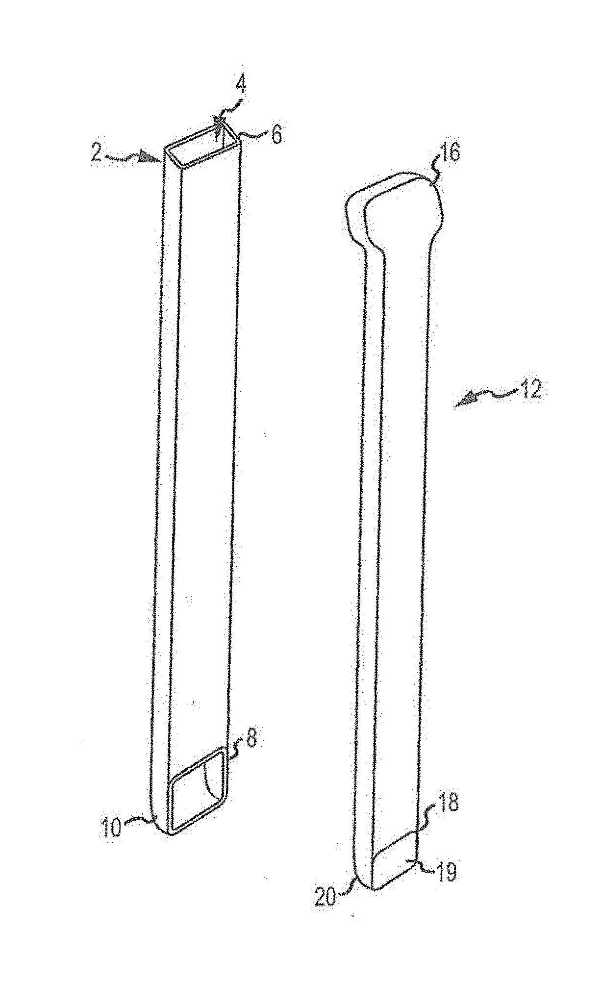
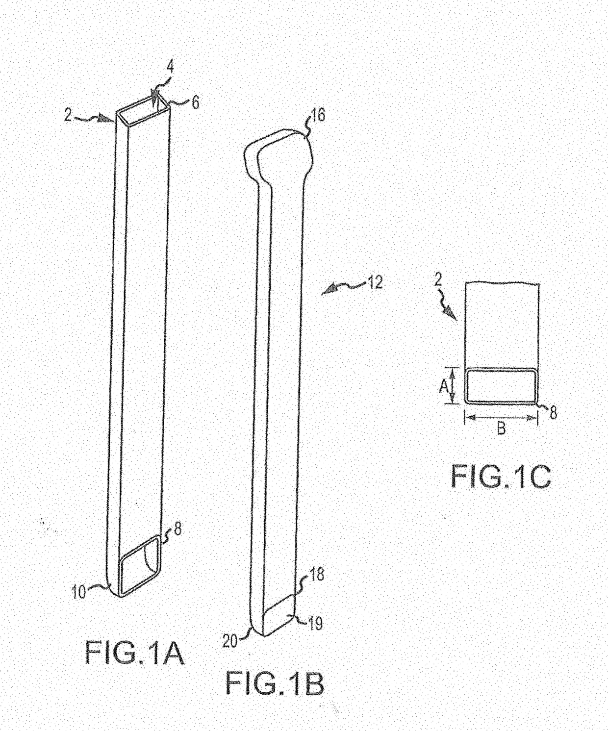
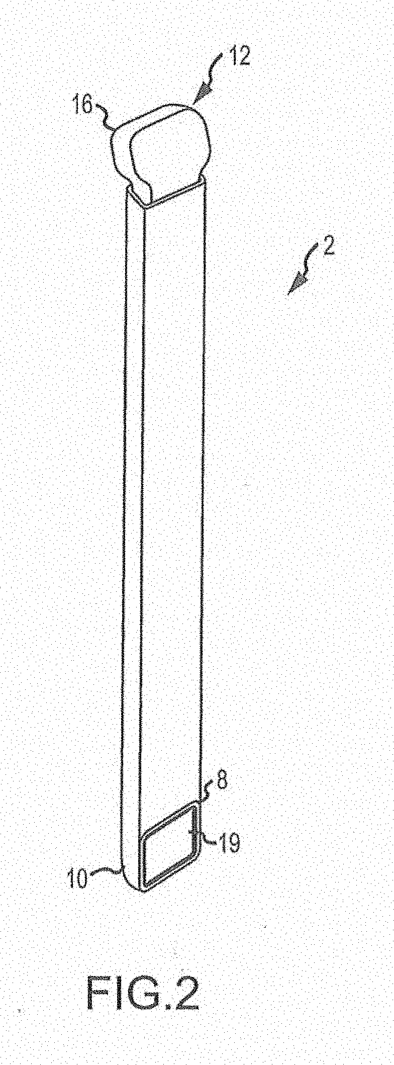
Instead, the device delivers graft material and / or a fusion cage using a hollow tube and plunger arrangement which is not a caulking gun style device and further, does not appreciably disrupt or block the user's view of the surgical site and / or enable precision delivery of bone graft material and / or a fusion cage to the surgical site.
Indeed, the device is distinctly unlike the chalking gun device of U.S. Pat. Appl.
The Sand device obstructs the view of the user of the delivery site.


