Utility mass flow gas meter

a gas meter and mass flow technology, applied in the field of utility gas meter, can solve the problems of inability to accurately measure the volume of gas, the reliability and accuracy of improvements had not been well proven and adopted for field deployment, and the gas volumetric data is not constant, so as to achieve the effect of easy installation and no additional cost of piping at installation

Active Publication Date: 2017-08-24
M TECH INSTR HLDG
View PDF0 Cites 17 Cited by
  • Summary
  • Abstract
  • Description
  • Claims
  • Application Information

AI Technical Summary

Benefits of technology

[0012]In another preferred embodiment, the invented all-electronic residential utility gas meter that is compatible with the mechanical diaphragm utility gas meter installation connecting schemes shall have the MEMS sensing assembly configured into a probe which is placed as an insertion one into the center of the main flow channel that is made with a Venturi structure for better flow stability. It is preferred that the insertion MEMS sensing assembly shall also be configured into a small Venturi pipe where the M EMS sensor shall be placed at the center throat of the inner Venturi structure. For further enhancement of gas flow stability and measurement repeatability, a pair of flow straightener and conditioner is placed at the inlet of the main flow channel. This invented meter with dual Venturi structure and a pair of flow straightener and conditioner ensures the high accuracy and performance that shall be critical for residential gas tariff applications.
[0017]For the adoption of the all-electronic utility gas meters for city gas metering, this invention provides a solution for direct replacement of the existing residential mechanical diaphragm meters without additional cost of piping at installation. The said invention shall have the desired performance for energy management and saving with the compensation of environmental variations such as, temperature and pressure. In particular the said meter can be data logged and remotely managed via network without the requirements of existing approaches with a mechanical reading to electronic data conversion that is not only costly but does not provide the desired performance. Further, the said invention provides data safety, easy installation, and maintenance.

Problems solved by technology

However, the gas volumetric data are not constant against temperature and pressure variations.
As the statistic consumption of the city gas will be about 5 times higher in winter compared to that, in summer, the city gas companies usually run a loss on the average and heavy government subsidy is often applied for the sustained operation of the city gas companies.
However, the reliability and accuracy of those improvements had not been well proven and adopted for the field deployment.
These efforts have not solved the basic requirements for gas data accuracy for custody transfer or tariff.
It has been hoped that the ultrasonic technology would be much easier to incorporate pressure and temperature sensors for better compensation of environmental variations on the gas metrology, but due to the cost and performance issues, the replacement of the mechanical meters has not been made possible as of today.
However, the construction and the electronics in the earlier 1990s were far more complicated to achieve the necessary metrology requirements.
In addition, the MEMS sensor probe had its wire exposed to the detecting gas media which was prone to reliability issues.
The meter configured had the potential with a low cost because of the simplified electronics but the products based on this patent covered only a single utility gas meter model which made the application impractical.
Jiang (C. Jiang et al., MEMS utility meters with exchangeable units, U.S. Pat. No. 8,994,552) and Yang (X. Yang et al, MEMS utility meters with, integrated. mass flow sensors, U.S. Pat. No. 9,109,935) have addressed the application requirements for utility gas applications for commercial and industrial users, but these designs could not be easily adopted for residential applications as the it is virtually impractical to alter the installation conditions for the vast numbers of the residential utility gas meters in the field.
Filed installation of the special mechanical connectors shall not only be extremely costly but the often limited space at installation in the residential conditions shall not allow such operations.

Method used


Image

  • Utility mass flow gas meter
  • Utility mass flow gas meter
  • Utility mass flow gas meter

Examples


Embodiment Construction

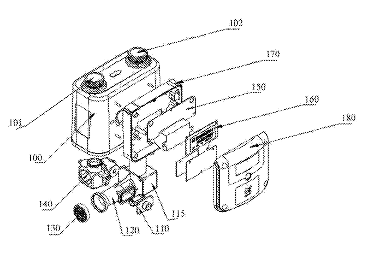
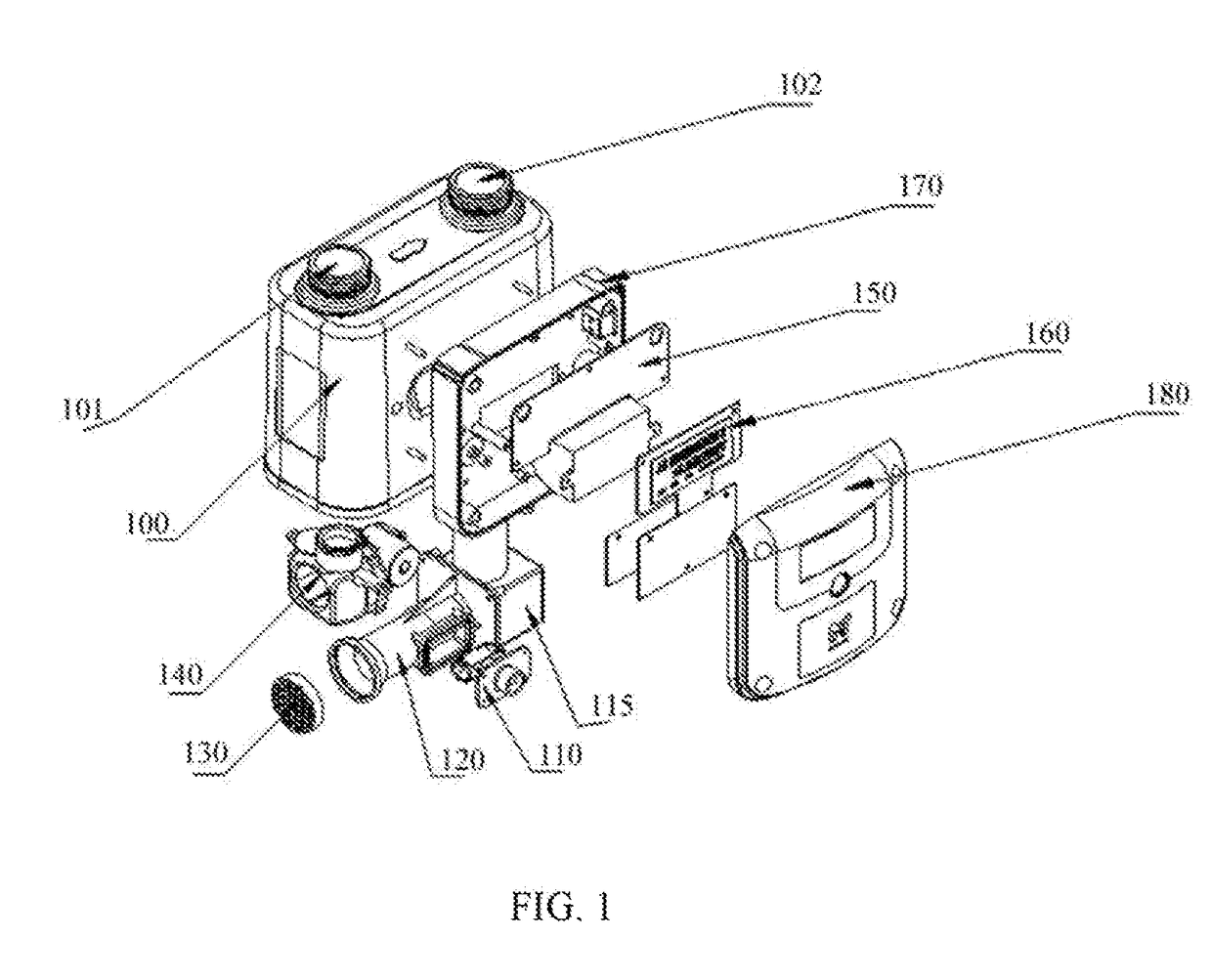
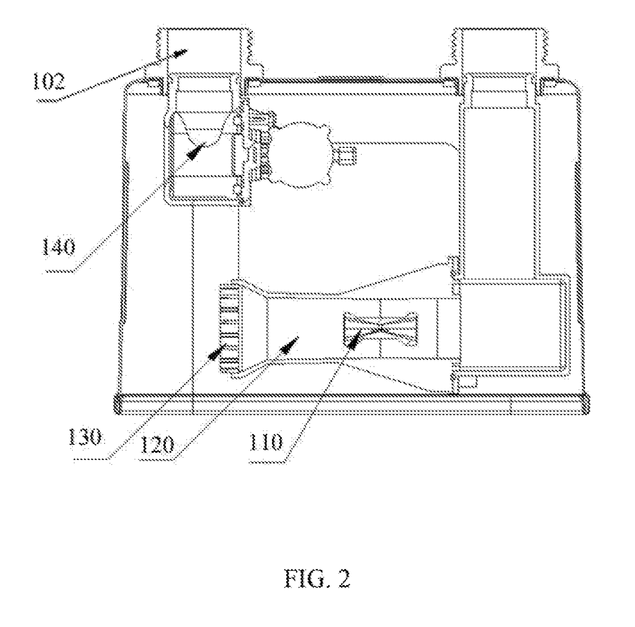
[0023]The explosive view of the all-electronic residential utility gas meter using MEMS sensing elements as the metrology unit disclosed in this invention is shown in FIG. 1. The said gas meter is designed with the meter body (100) with gas inlet (101) and gas outlet (102). The meter body is an enclosed cavity with tight hard sealing for gas leakage proof. The distances between gas inlet and outlet shall be the same as those specified for the mechanical diaphragm utility meter models such that the said meter installation shall not require any alternation of the city gas supply pipelines when doing a direct replacement of the existing mechanical meters by the said meter. Further, the pipe thread at the connectors for both the gas inlet and outlet shall he able to be customized according to the requirements for specific geographic regions. The connectors are preferably welded onto the meter body which is a cost saving approach with better leakage proof. The meter body (100) shall be m...


PUM


Abstract

An electronic utility gas meter using MEMS thermal mass flow sensor to measure gas custody transfer data in city gas metering application is disclosed in the present invention. The meter is designed to have its mechanical connectors identical to those of the current diaphragm gas meters while the insertion metrology unit guided channel is placed coaxially in the main flow channel inside the meter body with gas flow conditioning apparatus. The mechanical installation of the electronic utility gas meter then can be fully compatible with the current mechanical utility gas meters, which allows a seamless replacement. The electronic utility gas meter provides gas metrology that significantly improves the accuracy of the city gas metering, and provides additional benefits for data safety, enhanced gas chemical safety, billing alternatives and full data management either locally or remotely.

Description

BACKGROUND OF THE INVENTION[0001]1. Field of the Invention[0002]This invention relates to apparatus for measurement of natural gases in city gas metrology. Specifically this invention relates to an all-electronic utility gas metering using micro-machined silicon flow sensors or Micro Electro Mechanical Systems (MEMS) mass flow sensing technology to meter the city gas in the utility industry requiring custody transfer or tariff. This invention also provides the design and make of an all-electronic mass flow meter with remote data capability and other intelligent functions, which can be used to directly replace existing diaphragm gas meters for the utility industry without modification of the current installation schedules.[0003]2. Description of the Related Art[0004]Utility gas meters for city gas metering has been dominated b the mechanical diaphragm meters that have been invented some 170 years ago by a UK inventor, Thomas Glover. Since then, the materials that used to make the dia...

Claims


Application Information

Patent Timeline
Patent Type & Authority Applications(United States)
IPC IPC(8): G01F1/78G01F15/14G01D4/02G01F15/00
CPCG01F1/78G01F15/005G01D4/02G01F15/006G01F15/14Y02B90/20Y04S20/30
Inventor WONG, WAI TUNG IVANHUANG, LIJILING, KOWNG SHING
Owner M TECH INSTR HLDG
Why Eureka
Try Eureka