Method and apparatus for levitation additive welding of superalloy components

a technology of additive welding and superalloy metal, which is applied in the direction of mechanical equipment, turbines, manufacturing tools, etc., can solve the problems of over melting of the substrate, overheating of the molten metal layer, and overheating of the superheating layer, so as to facilitate the application of minimal heat, facilitate the precise orientation of the weld cladding layer, and increase the surface dimension

Inactive Publication Date: 2017-09-07
SIEMENS ENERGY INC
View PDF0 Cites 6 Cited by
  • Summary
  • Abstract
  • Description
  • Claims
  • Application Information

AI Technical Summary

Benefits of technology

[0003]Exemplary embodiments described herein additively weld superalloy components for turbine engines. In some embodiments, the weld material repairs a surface void in the component. In other embodiments, the superalloy component is clad with a weld layer, in order to increase its surface dimensions, or to manufacture a completely new component. In accordance with embodiments described herein, welding is performed by propelling a stream of powdered filler, which includes superalloy powder filler, through a nozzle at a powder stream mass flow rate, with pressurized gas. The powdered filler stream is melted and agglomerated into a continuous melt stream with a laser or arc heating source located downstream of the nozzle. Melt stream temperature is maintained 10 to 50 degrees Celsius above the component material's melting point, which provides sufficient superheat to enable fusion at the component weld site. The melt stream is levitated, within a magnetic field generated by at least one electromagnet coil that is oriented downstream of the heating source. The magnetic levitation facilitates a more precise orientation of the weld cladding layer at the component weld site, by counteracting gravitational forces imparted on the melt stream. In some embodiments, the levitated melt stream is enveloped within inert or partially inert gas, to protect it from atmospheric reaction, and is directed onto the superalloy component, by relative motion between the melt stream and the superalloy component. The welding system and welding method embodiments described herein facilitate application of minimal heat to the weld filler and the weld site of the component substrate that is necessary to achieve desired filler to substrate fusion, while avoiding excessive heat application that leads to post weld component cracking or other of the aforementioned excess heat application disadvantages.

Problems solved by technology

Many superalloy materials are negatively impacted by conventional welding processes, including arc welding and energy beam welding processes.
Such processes direct energy toward filler metal and the component substrate, inevitably delivering more heat than the minimum required to melt filler material and fuse it to the substrate.
Excess heat application causes one or more of molten metal superheating, substrate over melting, solidification cracking, physical distortion, and retained residual stresses within the material.
The retained residual stresses often cause additional cracking during post weld heat treatment cycles.

Method used


Image

  • Method and apparatus for levitation additive welding of superalloy components
  • Method and apparatus for levitation additive welding of superalloy components
  • Method and apparatus for levitation additive welding of superalloy components

Examples


Embodiment Construction

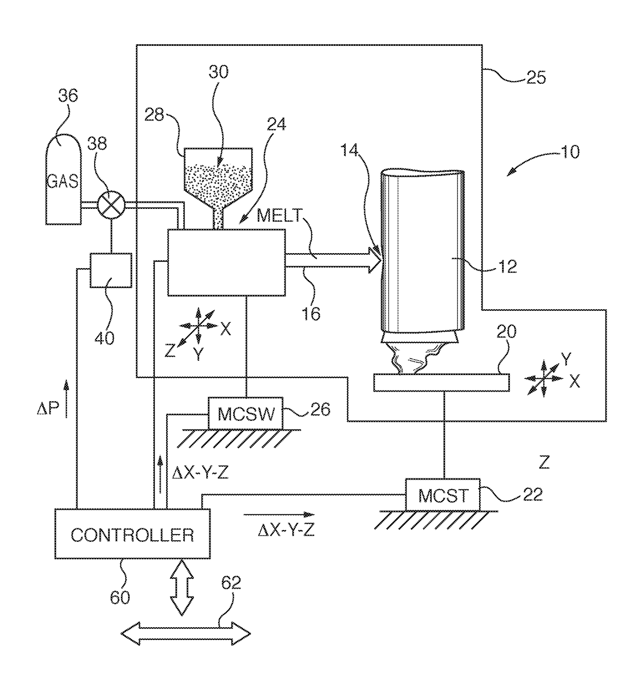
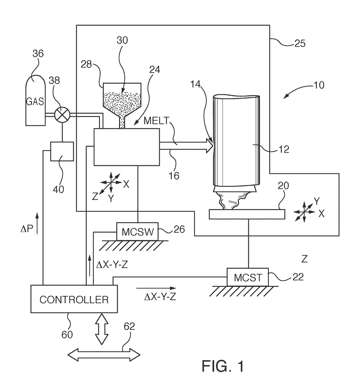
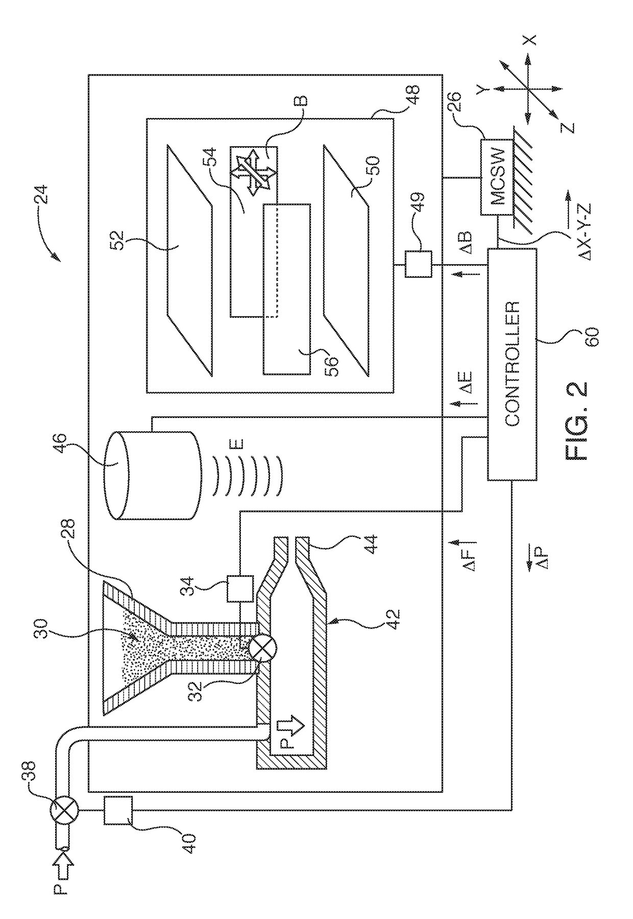
[0014]Exemplary embodiments of the invention are utilized in additive welding systems for superalloy components for turbine engines. In some embodiments, the added weld material repairs a surface void in the component, so that original component dimensional specifications are restored. In other embodiments, the superalloy component is clad with a weld layer, in order to increase its surface dimensions. In accordance with embodiments described herein, welding is performed by propelling a stream of powdered filler, which includes superalloy powder filler, through a nozzle at a powder stream mass flow rate, with pressurized gas. The powdered filler stream is melted and agglomerated into a continuous melt stream with a laser or arc heating source located downstream of the nozzle. In some embodiments, the pressurized propulsion gas or auxiliary downstream gas is inert, or partially inert, to shield heated and melted powder from atmospheric reaction; especially oxidation. The melt stream ...


PUM

PropertyMeasurementUnit
temperatureaaaaaaaaaa
melting pointaaaaaaaaaa
void depthaaaaaaaaaa

Abstract

Superalloy components for turbine engines are additively welded by propelling a stream of powdered filler, which includes superalloy powder filler, through a nozzle at a powder stream mass flow rate, with pressurized gas. The powdered filler stream is melted and agglomerated into a continuous melt stream with a laser or arc heating source located downstream of the nozzle. The melt stream is levitated within a magnetic field generated by at least one electromagnet coil that is oriented downstream of the heating source, and directed onto the superalloy component, by relative motion between the melt stream and the superalloy component.

Description

TECHNICAL FIELD[0001]The invention relates to additive weld cladding of superalloy metal components of turbine engines, for example, to repair voids or build up surface dimensions of an existing superalloy component, or to manufacture a new part. More particularly, the invention relates to additive weld cladding or repair of voids in superalloy metal components by creating a continuous weld melt stream from agglomerated powder filler with a heat source, such as a laser or arc generator, and levitating the weld melt stream with an electromagnet coil, so that the weld stream is applied to the superalloy component.BACKGROUND[0002]Components of combustion turbine engines, such as blades or vanes, are often cast with nickel-, iron-, or cobalt-based superalloy materials. Many superalloy materials are negatively impacted by conventional welding processes, including arc welding and energy beam welding processes. Such processes direct energy toward filler metal and the component substrate, i...

Claims


Application Information

Patent Timeline
Patent Type & Authority Applications(United States)
IPC IPC(8): B23P6/00B23K9/04B23K9/23B23K9/095B23K26/34B23K26/14B23K26/70B23K26/08B23K9/00B23K9/32
CPCB23P6/007B23K9/0026B23K9/04B23K9/23B23K9/324B23K9/0953B23K26/1464B23K26/702B23K26/083B23K26/0869B23K26/34B23K26/144B23K2101/001
Inventor BRUCK, GERALD J.
Owner SIEMENS ENERGY INC
Why Eureka
Try Eureka