Fuel cell system and method for operating a fuel cell system

a fuel cell and system technology, applied in the direction of batteries/cells, electrochemical generators, transportation and packaging, etc., can solve the problems of parasitic power consumption of these components, difference between the electrical power produced by the stack p/sub>stack/sub>and the parasitic power consumption p/sub>aux/sub>, and decrease of available useful power, etc., to achieve optimal fuel cell system dynamic, high degree of interaction, and optimal efficiency

Active Publication Date: 2017-09-14
AUDI AG
View PDF1 Cites 7 Cited by
  • Summary
  • Abstract
  • Description
  • Claims
  • Application Information

AI Technical Summary

Benefits of technology

[0013]The disclosure is now based on the task of proposing a fuel cell system and a method for operating a fuel cell system, wherein both an optimal efficiency and an optimal dynamic

Problems solved by technology

The power consumption of these components can be called a parasitic power consumption Paux, since it must indeed be provided by the fuel cell stack but is not available to external consumers.
The net power available to external consumers of the fuel cell system Pnet thus, results as the difference of the electrical power produced by the stack Pstack and the parasitic power consumption Paux.
Particularly at low load, for example as a result of a low current draw in standby mode, the available useful power decreases in proporti

Method used


Image

  • Fuel cell system and method for operating a fuel cell system
  • Fuel cell system and method for operating a fuel cell system
  • Fuel cell system and method for operating a fuel cell system

Examples


Embodiment Construction

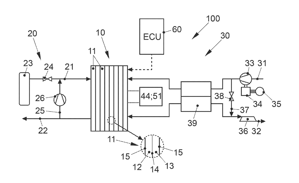
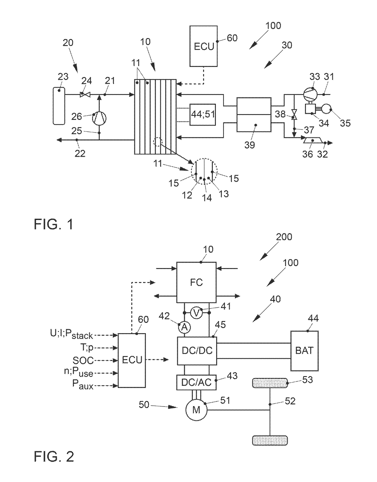
[0045]FIG. 1 shows a fuel cell system, denoted with 100 overall, according to a preferred embodiment of the present disclosure. The fuel cell system 100 is part of a vehicle not shown in further detail, in particular of an electric vehicle, which comprises an electric traction motor, which is supplied with electrical energy by the respective fuel cell system 100.

[0046]The fuel cell system 100 comprises as core components a fuel cell stack 10, which comprises a plurality of individual cells 11, which are arranged in the form of a stack and which are formed by alternately stacked membrane electrode assemblies (MEAs) 14 and bipolar plates 15 (see detailed view). Each individual cell 11 thus respectively comprises an MEA 14 with an ion-conductive polymer electrolyte membrane not shown in more detail here and catalytic electrodes arranged thereon on both sides. These electrodes catalyze the respective partial reaction of the fuel conversion. The anode and cathode electrodes are designed ...


PUM


Abstract

The disclosure relates to a fuel cell system comprising a fuel cell stack for providing an electrical power Pstack depending on a power demand, at least one auxiliary unit for operating the fuel cell stack with an electrical power consumption Paux, at least one consumer with an electrical power request Puse, and a control unit for regulating the power demand as well as a method for controlling such a fuel cell system. It is provided that the control unit is configured to selectively operate the fuel cell system in a first operating mode or in a second operating mode, whereby the fuel cell stack is turned off depending on the operating mode upon the falling below of an optimal efficiency degree operating point P(ηmax) of the fuel cell system or a minimum operating point Pmin of the fuel cell stack. In particular, at least one auxiliary unit is also turned off in the first operating mode, when the optimal efficiency degree operating point decreases.

Description

BACKGROUND[0001]Technical Field[0002]The disclosure relates to a fuel cell system and a method for operating a fuel cell system. The disclosure further relates to a vehicle with such a fuel cell system.[0003]Description of the Related Art[0004]Fuel cells utilize the chemical conversion of a fuel, with oxygen to water, in order to generate electrical energy. For this purpose, fuel cells contain the so-called membrane electrode assembly (MEA) as a core component, which is an arrangement of an ion-conducting (often proton-conducting) membrane and of a catalytic electrode (anode and cathode), respectively arranged on both sides of the membrane. Generally, the fuel cell is constituted by a plurality of MEAs arranged in the stack, whose electrical power outputs accumulates. Between the individual membrane electrode assemblies, bipolar plates (also called flow field plates or separator plates) are usually arranged, which ensure a supply of the individual cells with the operating media, i.e...

Claims


Application Information

Patent Timeline
IPC IPC(8): H01M8/04828H01M16/00B60L11/18
CPCH01M8/0494B60L11/1883H01M2008/1095H01M2250/20H01M16/006H01M8/04H01M8/04298H01M8/04947H01M8/04604H01M8/04619H01M8/04626B60L50/72Y02T90/40Y02E60/50Y02E60/10
Inventor WEALEXANDERDUVEL, MARCSCHRODER, HENDRIK
Owner AUDI AG
Why Eureka
Try Eureka