
Circuit and method to reduce fundamental and modulation spurs with spread spectrum

Active Publication Date: 2017-09-21
TEXAS INSTR INC
View PDF3 Cites 4 Cited by
  • Summary
  • Abstract
  • Description
  • Claims
  • Application Information

AI Technical Summary

Benefits of technology

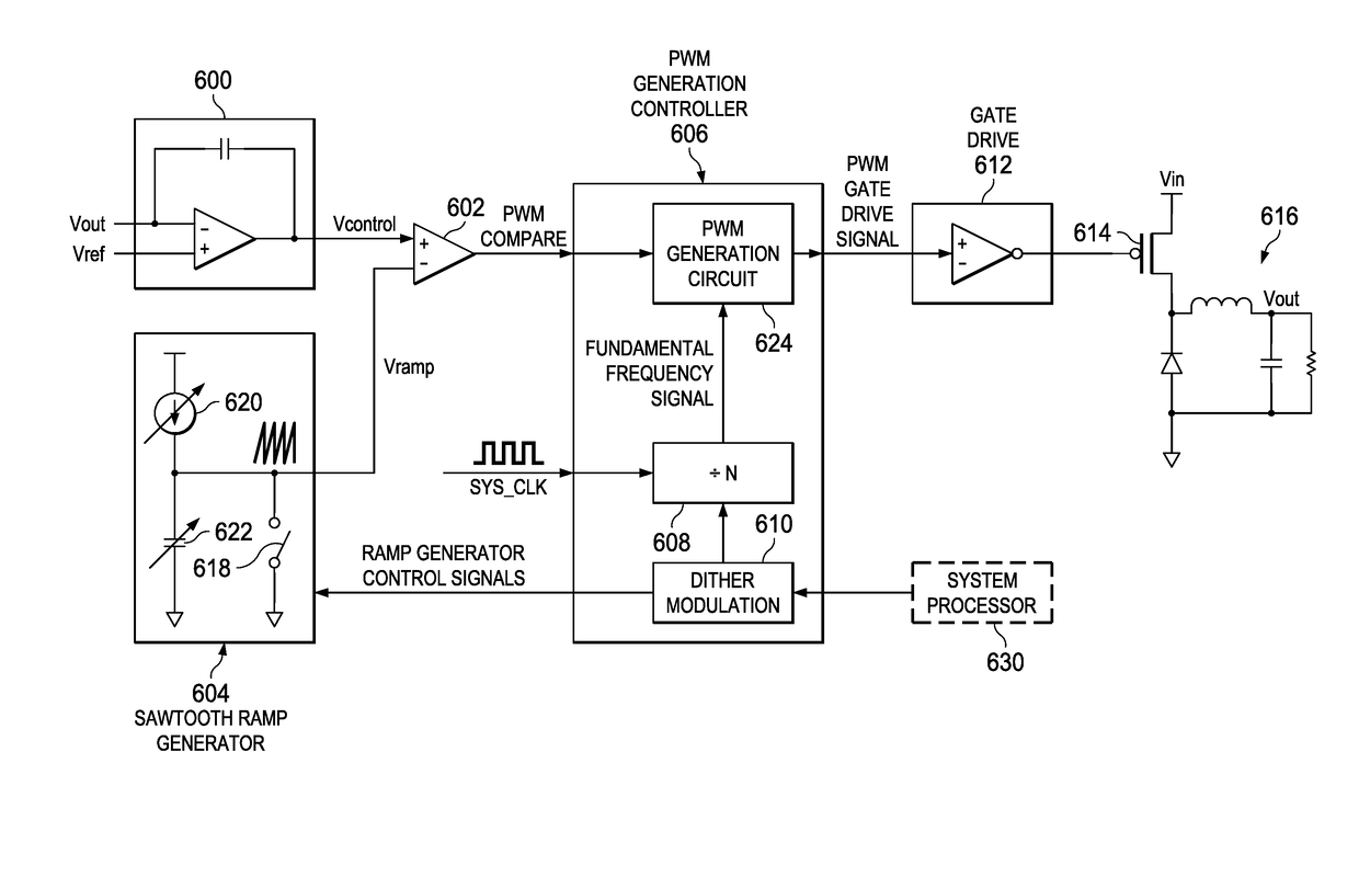
The present invention offers improved benefits in reducing EMI (electromagnetic interference) in switching power supplies compared to previous methods.

Problems solved by technology

However, board level methods to mitigate EMI through layout techniques fail to address the source of noise generation.
Best practice layout techniques can only mitigate the introduction of additional EMI noise by minimizing current conducting loop area, filtering, shielding, and use of ground planes.
Furthermore, these methods increase system cost as well as solution size.
This additional spectral noise is further exacerbated when optimizing for the CISPR / FCC specifications and results in modulation spurs being placed in the audio band around 9 kHz.
This may cause an undesirable hum in switching power supplies operating in the MHz range.
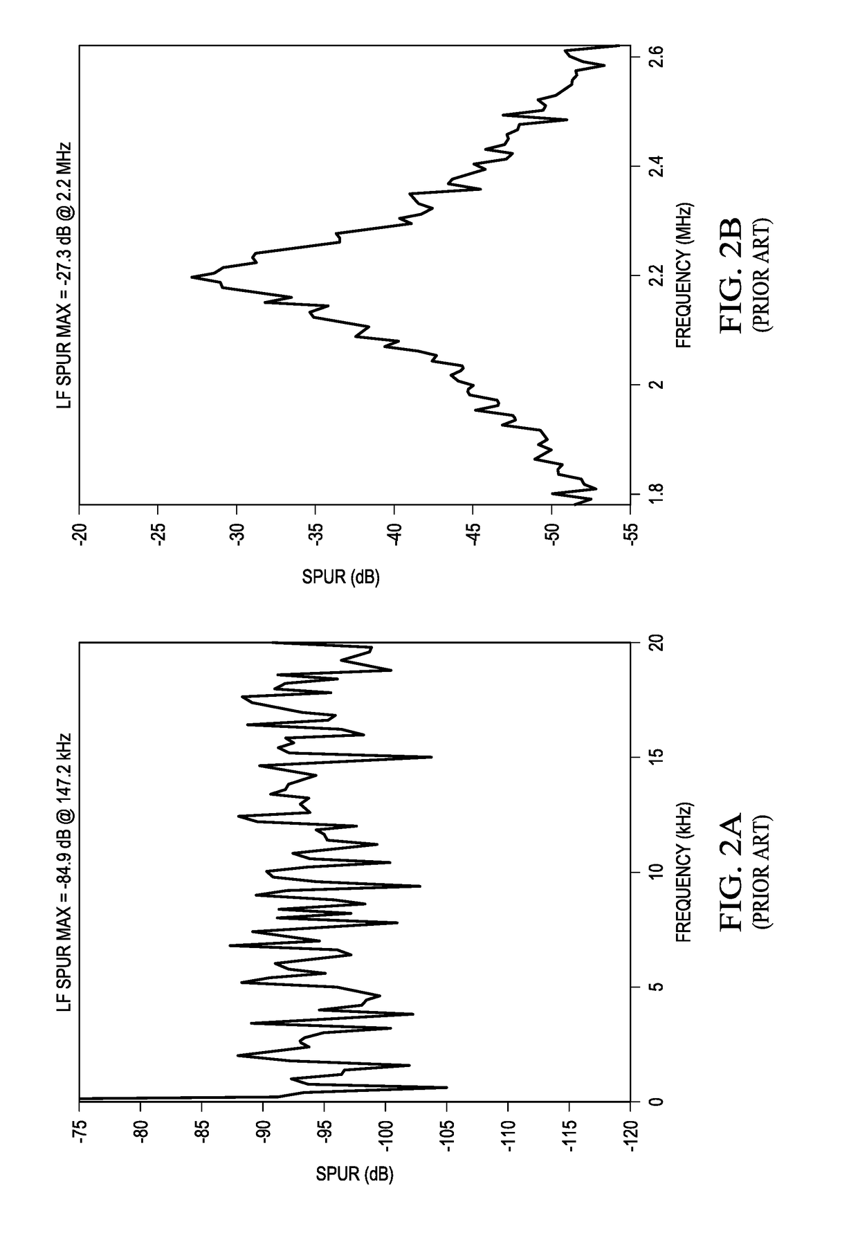
Pseudorandom variation of the fundamental frequency, however, provides inferior fundamental spur reduction but decreases other spectral content.

Method used


Image

  • Circuit and method to reduce fundamental and modulation spurs with spread spectrum
  • Circuit and method to reduce fundamental and modulation spurs with spread spectrum
  • Circuit and method to reduce fundamental and modulation spurs with spread spectrum

Examples


Embodiment Construction

[0022]The preferred embodiments of the present invention provide significant advantages over the prior art in EMI reduction of switching power supplies as will become evident from the following detailed description.

[0023]Referring to FIG. 5, there is a diagram illustrating a Modulation Curve having spread spectrum Fundamental Frequencies and a Modulation Frequency. Terms defined in this diagram will be used in the following discussion to explain embodiments of the present invention. The diagram shows frequency variation or dithering as a function of time for one modulation cycle. The modulation cycle has a period tm and modulation frequency of 1 / tm. The modulation curve illustrates fundamental frequency variations between minimum (fmin) and maximum (fmax) frequencies distributed about center frequency fc. A positive slope 500 of the modulation curve is defined by an incremental frequency increase (df) and a corresponding incremental time increase (dt) Likewise, a negative slope 502 ...


PUM


Abstract

A method of generating a spread spectrum signal is disclosed. The method includes selecting a first pseudorandom slope for a modulation curve. A current frequency on the modulation curve is selected. An oscillating signal is produced at the current frequency for a respective time. The current frequency is set to a next frequency on the modulation curve. The steps of producing an oscillating frequency and setting the current frequency to a next frequency are repeated until the current frequency is a final frequency on the modulation curve.

Description

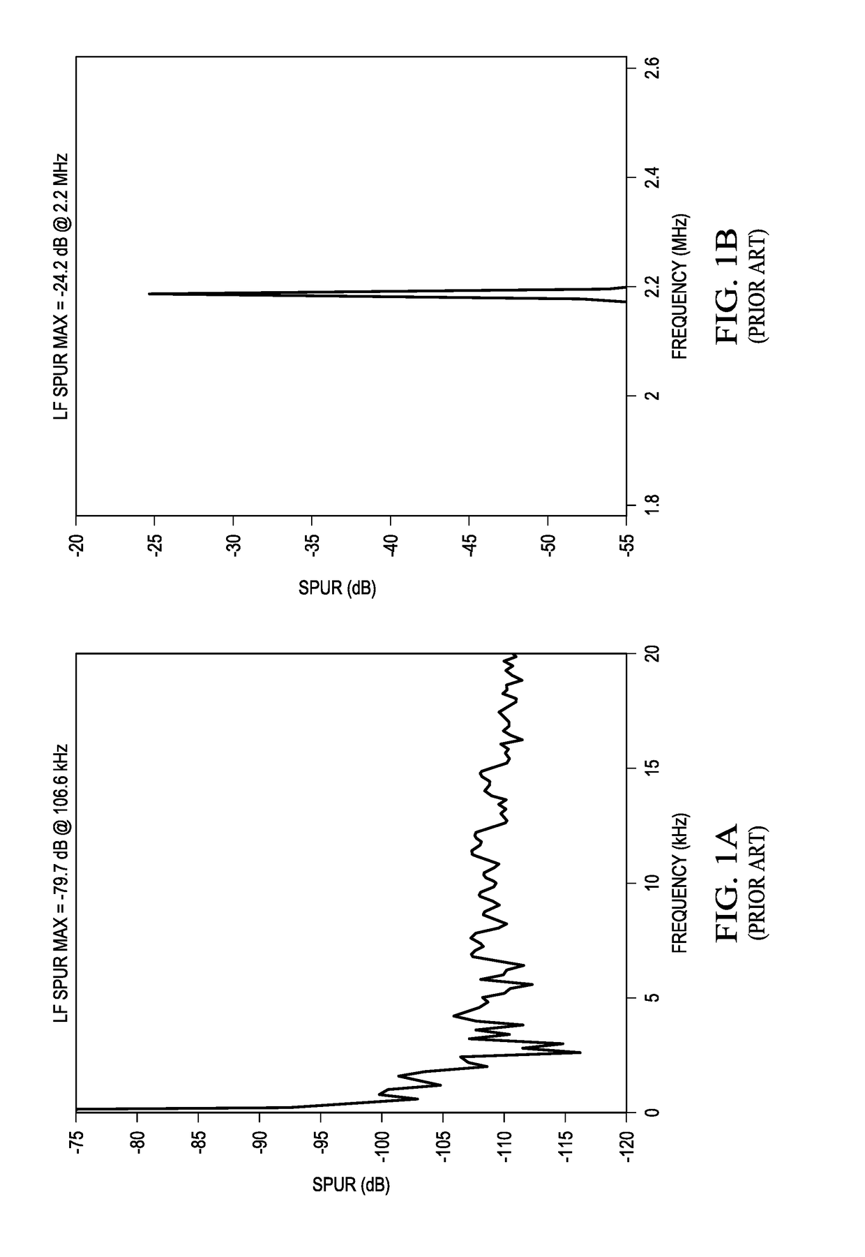
BACKGROUND OF THE INVENTION[0001]Embodiments of the present invention relate to spread spectrum solutions for electromagnetic interference (EMI) in switched mode power supplies by utilization of spread spectrum switching frequencies.[0002]Switched mode power supplies, due to the nature of their switching behavior, introduce spectral spurs at their fundamental switching frequency and corresponding harmonics. These spurs are referred to as electromagnetic interference (EMI) and are regulated by the CISPR, FCC and other standards. FIG. 1B illustrates an EMI spur for a 2.2 MHz fundamental frequency at −24.2 dB. This is for a square wave with no spread spectrum switching. FIG. 1A illustrates a corresponding low frequency spur at −79.7 dB associated with harmonics of the 2.2 MHz fundamental frequency. Board level solutions to such interference typically utilize a combination of shielding or filter techniques to suppress EMI spurs in order to comply with regulations and design specificatio...

Claims


Application Information

Patent Timeline
IPC IPC(8): H04B1/69
CPCH04B1/69H03C3/0916H02M1/44H02M3/155H02M3/156
Inventor YU, THEODORE ERNESTRAMADASS, YOGESH KUMAR
Owner TEXAS INSTR INC
Learn More