
Extender For Optical Access Communication Network

a technology of optical access and communication network, applied in the field of telecommunications, can solve the problems of increasing the cost of the pon system, limiting the reach and splitting ratio of the pon, and complicating the onus structur

Inactive Publication Date: 2017-09-21
TELEKOM MALAYSIA BERHAD
View PDF26 Cites 15 Cited by
  • Summary
  • Abstract
  • Description
  • Claims
  • Application Information

AI Technical Summary

Benefits of technology

The invention describes an optical line terminal that can transmit data of different wavelengths through a network using a time division multiplexing scheme. The terminal includes one or more downstream signal processing means for generating a downstream signal and converting data, a wavelength division multiplexing means for combining the serial data of different wavelengths, and one or more upstream signal processing means for extracting data of an upstream signal. The terminal also includes an extender which includes optical amplifiers for amplifying the upstream and downstream signals, a Raman wavelength division multiplexing module for separating and combining data signal and pump light, and a Raman pump unit coupled to the Raman wavelength division multiplexing module for providing Raman amplification to the upstream and downstream signals. The optical distribution network includes optical passive splitters for splitting the signals evenly. The patent provides technical solutions for transmitting data of different wavelengths in a network.

Problems solved by technology

The main drawbacks of PON are that the reach and splitting ratio of a PON is limited by the optical signal losses and strength.
To adopt such approach, proper modifications such as the implementation of relevant electrical modules and cooling system on the PON fiber distribution cabinets (FDC) are needed and this will increase the cost of the PON system.
However, the approach will complicate the architecture of the ONUs, which is unfavourable.
In addition to that, the use of Optical-Electrical-Optical design in the prior system limits their transmission rate.

Method used


Image

  • Extender For Optical Access Communication Network
  • Extender For Optical Access Communication Network

Examples


Embodiment Construction

[0018]The invention will now be described in greater detail, by way of example, with reference to the drawings.

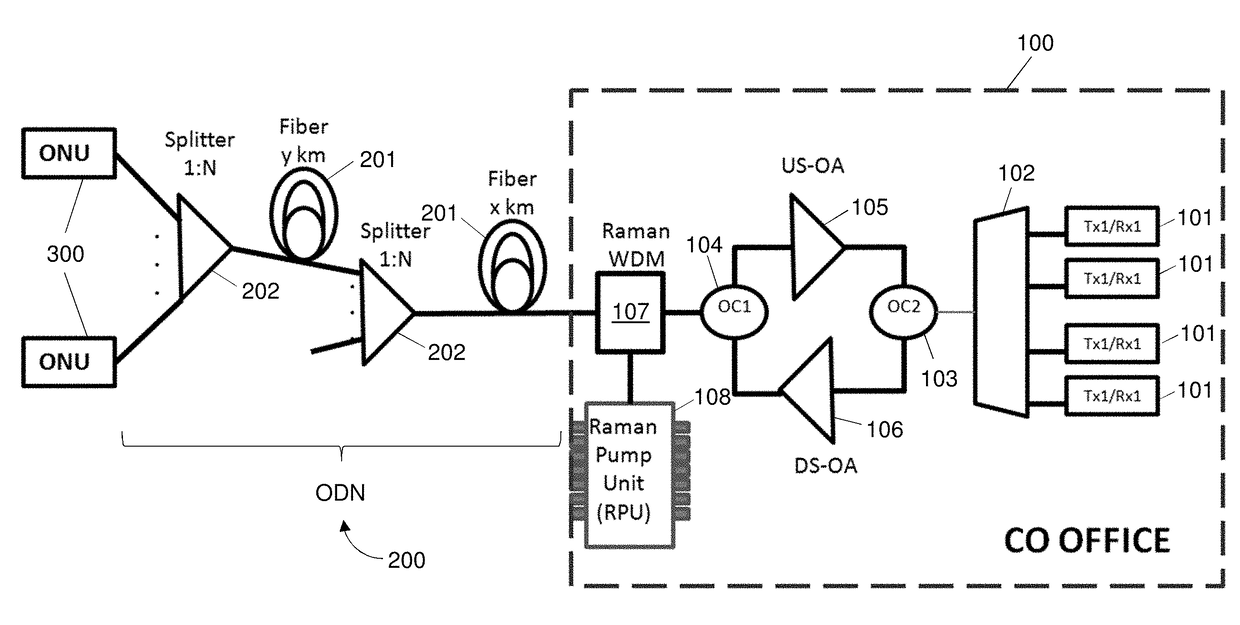
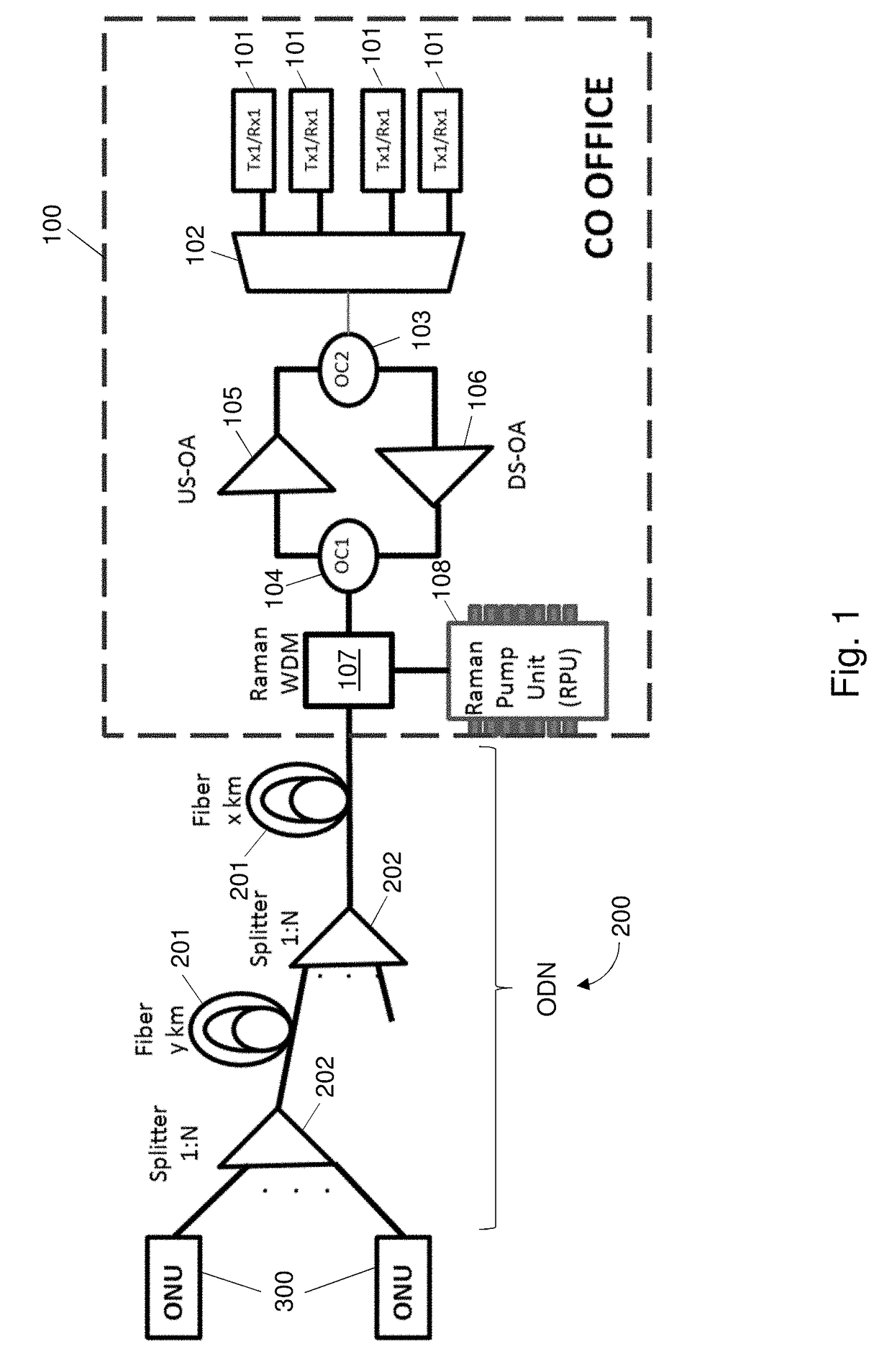
[0019]FIG. 1 illustrates an exemplary passive optical network (PON) system formed in accordance with preferred embodiments of the invention. The PON system includes an optical line terminal (OLT) 100 configured to provide a service using an optical signal of a different wavelength in Time Division Multiplexing scheme, a plurality of optical network units (ONUs) 300 configured to utilizes the service that is provided by the OLT 100, and an optical distribution network (ODN) 200 configured to transmit downstream optical signals from the OLT 100 to the ONUs 300 and transmit upstream optical signals from the ONUs 300 to the OLT 100. The PON is preferably a time wavelength division multiplexing-passive optical network (TWDM-PON). The mentioned service can include voice service or voice over IP, network data, picture, and video. The ODN 200 is a section sandwiched between the OLT...


PUM


Abstract

The present invention discloses an optical line terminal that includes one or more downstream signal processing means for generating a downstream signal, and converting data of the downstream signal into a serial data; a wavelength division multiplexing means for combining the serial data of different wavelengths together and then performing transmission of the combined signals; and one or more upstream signal processing means for extracting data of an upstream signal from the wavelength division multiplexing means. The terminal includes an extender including a first optical amplifier for amplifying the upstream signal, a second optical amplifier for amplifying the downstream signal, a Raman wavelength division multiplexing module for separating and combining data signal and pump light from Raman pump unit, and a Raman pump unit coupled to the Raman wavelength division multiplexing module to provide Raman amplification to the upstream and downstream signals.

Description

CROSS-REFERENCE TO RELATED APPLICATIONS[0001]The present application claims the priority benefit of Malaysian Patent Application No. PI 2016000498, filed Mar. 17, 2016, which is incorporated by reference in its entirety.FIELD OF INVENTION[0002]The invention relates to telecommunications. More particularly, the invention relates to an extender for optical access networking.BACKGROUND OF THE INVENTION[0003]A passive optical network (PON) is a point-to-multipoint, fiber-to-the-premises, broadband network architecture in which unpowered (“passive”) optical splitters are used to enable a single optical fiber to serve multiple customer premise locations. Conventionally, a PON includes an optical line terminal (OLT) at a service provider's central office (CO) and a multiplicity of optical network units or terminals (ONUs or ONTs, hereinafter referred to as “ONUs”) located at or in the vicinity of end users. The OLT is linked to the plurality ONUs via an optical distribution network (ODN) w...

Claims


Application Information

Patent Timeline
IPC IPC(8): H04J14/02H04B10/291
CPCH04J14/0221H04J14/0247H04J14/0223H04B10/2916H04B10/272H04B10/2972H04J14/0282
Inventor BINTI AHMAD, ASMAHANIMTARSONO, DEDYBIN ABDUL KADIR, MUHAMMAD ZAMZURIMANAF, ZULHEDRY ABDUL
Owner TELEKOM MALAYSIA BERHAD
Learn More