Honeycomb structure

a honeycomb structure and honeycomb technology, applied in the field of honeycomb structure, can solve the problems of not taking into account the use state of the honeycomb structure as described above, and it is difficult to achieve simultaneous problems to increase the amount of catalyst, so as to reduce the amount of catalyst to be loaded, inhibit the increase and effectively reduce the effect of pressure loss during us

Active Publication Date: 2017-09-28
NGK INSULATORS LTD
View PDF0 Cites 8 Cited by
  • Summary
  • Abstract
  • Description
  • Claims
  • Application Information

AI Technical Summary

Benefits of technology

[0033]A honeycomb structure of the present invention is capable of increasing an amount of a catalyst to be loaded and inhibiting increase of pressure loss during use. In particular, the honeycomb structure of the present invention is characterized in that a thickness of partition walls and a cell density are set to predetermined values, whereas a product of an inflow side filtration area G (cm2 / cm3) and a pore volume ratio A (cm3 / L) is set to be 1800 cm2 / L or more and 3200 cm2 / L or less. According to such a constitution, in the honeycomb structure of the present invention, even when a comparatively large amount of catalyst is loaded onto the partition walls, it is possible to effectively decrease pressure loss during use.

Problems solved by technology

Further, in the technology described in Patent Document 1, there has been the problem that such a use state of the honeycomb structure as described above is not taken into consideration at all.
Consequently, in a porous honeycomb filter described in Patent Document 2, there has been the problem that it is difficult to simultaneously achieve problems to increase the amount of the catalyst to be loaded and to inhibit increase of pressure loss during use because the problems might cause an antinomy relation.

Method used


Image

  • Honeycomb structure
  • Honeycomb structure
  • Honeycomb structure

Examples


example 1

[0064]20 parts by mass of pore former, 30 parts by mass of dispersing medium, 5 parts by mass of organic binder and 0.5 parts by mass of dispersing agent were added to 100 parts by mass of cordierite forming raw material, and mixed and kneaded to prepare a kneaded material. As the cordierite forming raw material, there were used alumina, aluminum hydroxide, kaolin, talc, and silica. Water was used as the dispersing medium, a foamable resin having an average particle diameter of 30 μm was used as a pore former, hydroxypropyl methylcellulose was used as the organic binder, and a surfactant was used as the dispersing agent.

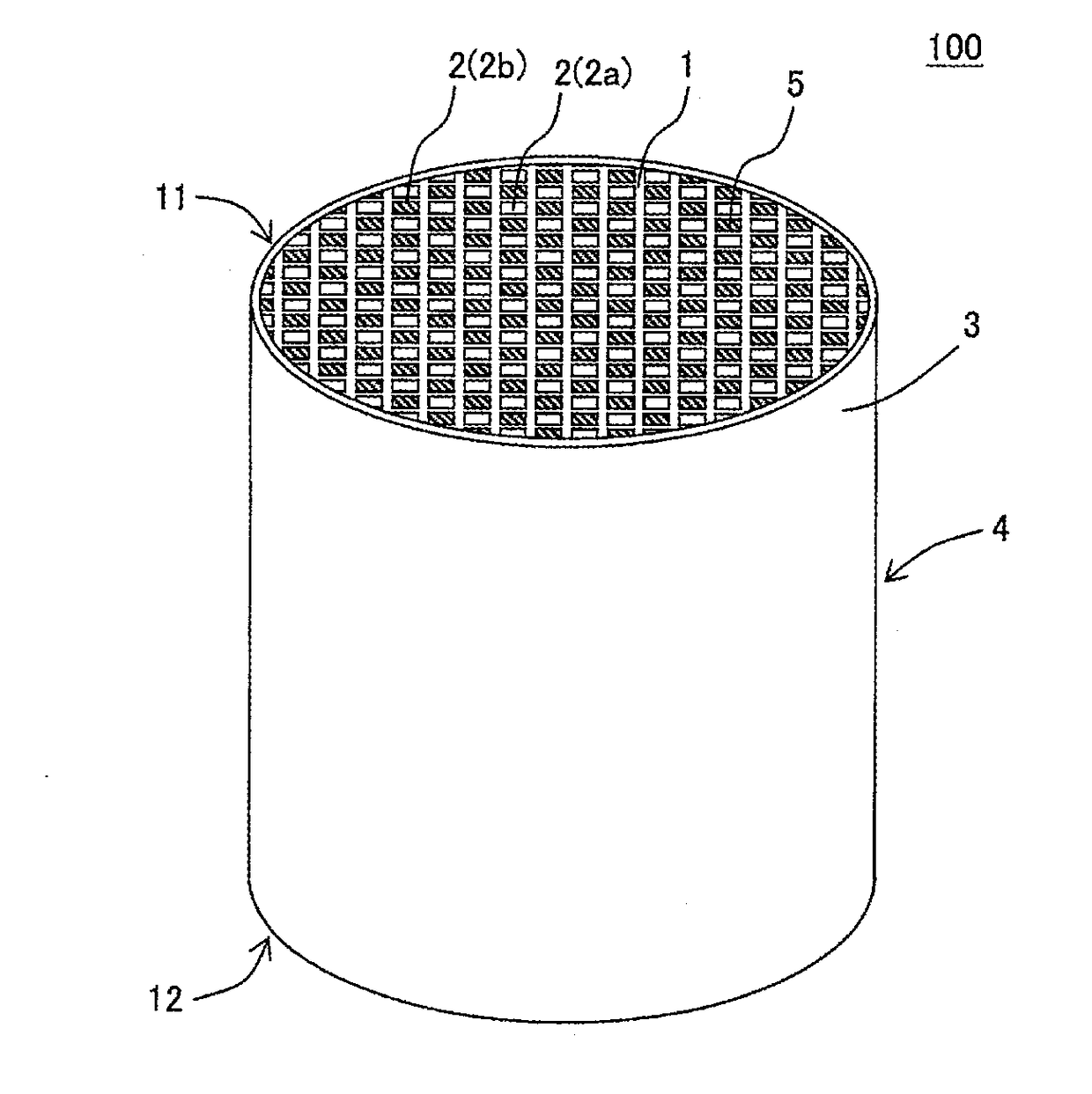
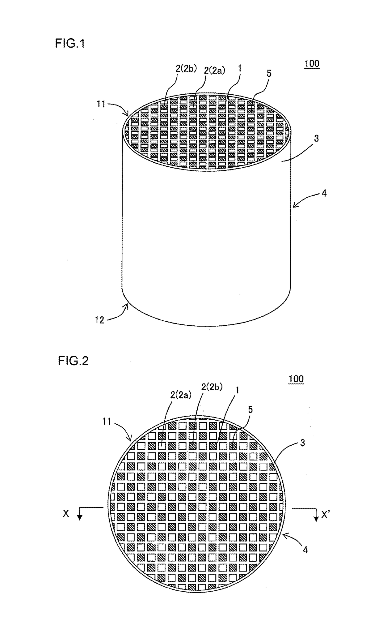
[0065]Next, the kneaded material was extruded by using a honeycomb formed body preparing die, to obtain a honeycomb formed body having a round pillar shape as a whole. A cell shape of the honeycomb formed body was quadrangular.

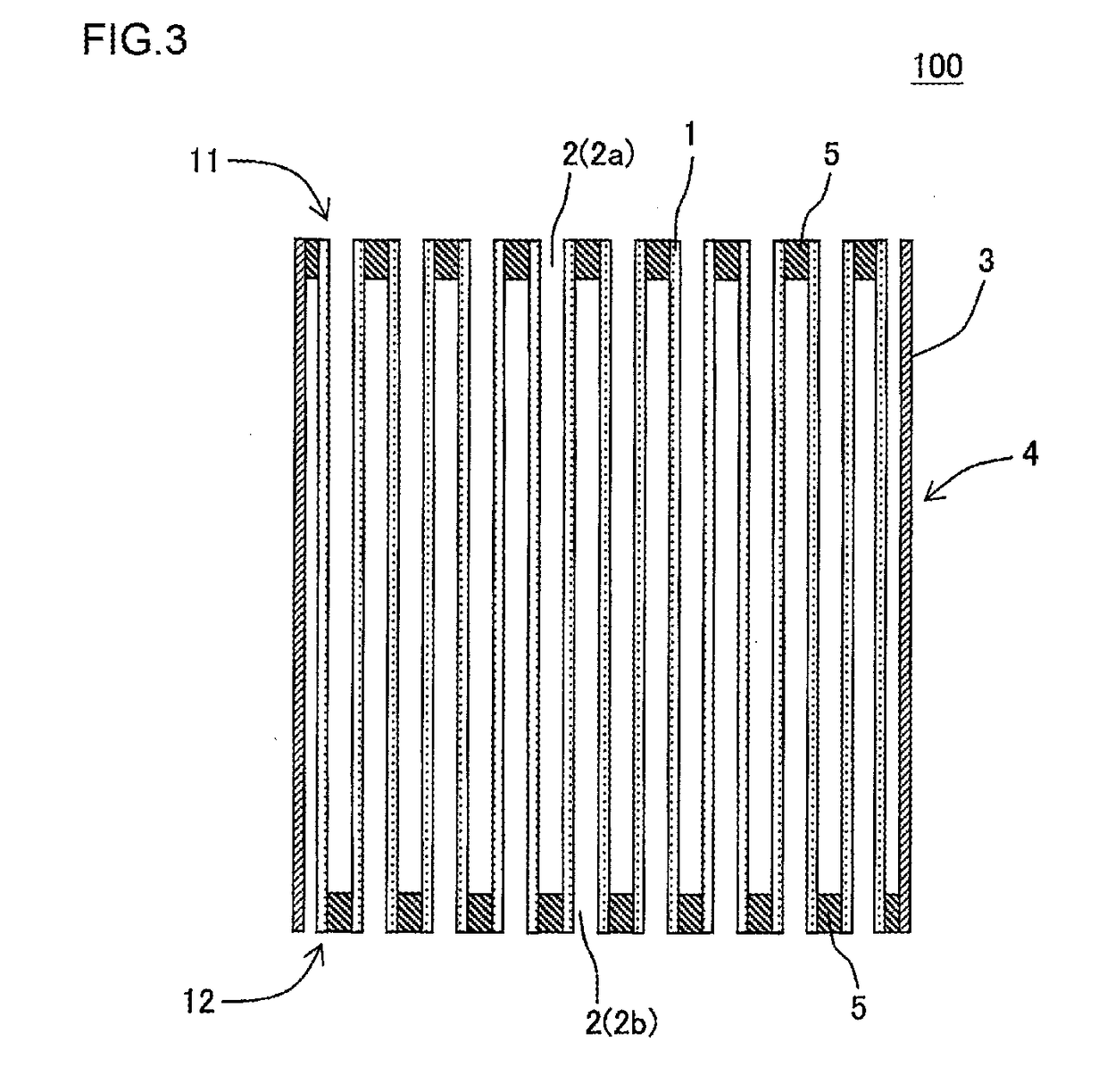
[0066]Next, the honeycomb formed body was dried with a microwave drier, and further completely dried with a hot air dryer, and both end faces ...

examples 2 to 23

[0081]The procedure of Example 1 was repeated except that a cell structure of a honeycomb structure, pore characteristics and a shape of the honeycomb structure were changed as shown in Table 1, to prepare honeycomb structures. In Examples 2 to 23, a porosity was adjusted in accordance with an amount of a foamable resin and an amount of an organic binder. Furthermore, in Examples 2 to 23, a mean pore size was adjusted in accordance with particle diameters of the foamable resin, particle diameters of a cordierite forming raw material and a firing temperature. Furthermore, when Table 1 shows “quadrangular and octagonal” in a column of “cell shape” among columns of the cell structure, it is indicated that a shape of inflow cells is octagonal and a shape of outflow cells is quadrangular.


PUM

PropertyMeasurementUnit
thicknessaaaaaaaaaa
thicknessaaaaaaaaaa
pore sizeaaaaaaaaaa

Abstract

The honeycomb structure includes a honeycomb structure body having porous partition walls, and a plugging portion disposed in one of open ends of each cell, a thickness of the partition walls is 0.30 mm or more and 0.51 mm or less, a cell density is 30 cells/cm2 or more and 93 cells/cm2 or less, a filtration area (cm2) of inflow cells included per cm3 of the honeycomb structure body is defined as an inflow side filtration area G (cm2/cm3), a value obtained by dividing a pore volume Vp (cm3) formed in the partition walls by a total volume Va (L) including the cells is defined as a pore volume ratio A (cm3/L), and in this case, a product of the inflow side filtration area G (cm2/cm3) and the pore volume ratio A (cm3/L) is 1800 cm2/L or more and 3200 cm2/L or less.

Description

[0001]The present application is an application based on JP 2016-064656 filed on Mar. 28, 2016 with Japan Patent Office, the entire contents of which are incorporated herein by reference.BACKGROUND OF THE INVENTION[0002]Field of the Invention[0003]The present invention relates to a honeycomb structure, and more particularly, it relates to a honeycomb structure which is capable of increasing an amount of a catalyst to be loaded and inhibiting increase of pressure loss during use.[0004]Description of the Related Art[0005]In recent years, consciousness for environmental problems has increased in the whole society, and in a technical field in which fuel is burnt to generate power, various technologies have been developed to remove toxic components such as nitrogen oxides from an exhaust gas generated during the burning of the fuel. For example, various technologies have been developed to remove toxic components such as nitrogen oxides from the exhaust gas emitted from a car engine. Duri...

Claims


Application Information

Patent Timeline
Patent Type & Authority Applications(United States)
IPC IPC(8): B01J35/04F01N3/20F01N3/28B01D46/24B01D53/94
CPCB01J35/04B01D46/247B01D46/2474B01D53/9418B01D2255/915F01N3/2066B01D2255/20761B01D2255/50F01N3/2842B01D53/9413B01J35/10B01D46/24492B01D46/2484B01D46/2482B01D2255/2092B01D2255/504B01D2255/9155B01D2255/9205B01D2258/012F01N3/021F01N3/0222F01N3/035F01N2260/06F01N2330/30F01N2330/48B01J35/002Y02A50/20Y02T10/12B01D46/2429
Inventor TERANISHI, MAKOTOKATO, YASUSHIMATSUYA, JUNKIHONDA, TAKAHIROKONDO, TAKAHIRO
Owner NGK INSULATORS LTD
Why Eureka
Try Eureka