Fuel cell system and fuel cell operating method

a fuel cell and operating method technology, applied in the field of fuel cell systems, can solve the problems of deteriorating reliability in a safety, requiring excessive size of the catalyst combustor, so as to reduce the amount of catalyst needed for processing fuel gas and improve heat energy recovery efficiency.

Inactive Publication Date: 2005-11-17
NISSAN MOTOR CO LTD
View PDF3 Cites 9 Cited by
  • Summary
  • Abstract
  • Description
  • Claims
  • Application Information

AI Technical Summary

Benefits of technology

[0005] However, since the related art technology takes the form of the structure wherein anode off-gas and cathode off-gas are combusted at the mixture ratio lying at a value deviated from the explosion limit, in case of combusting mixed gas with the mixture ratio falling at a value less than an explosion lean-limit, the flow rates of oxidant gas needed for combustion increase and, therefore, the amount of catalyst needed for processing fuel gas is increased. This results in an issue wherein the catalytic combustor is required to be formed in an excessively large size or a recovery efficiency of heat energy is deteriorated due to the combustion temperature being relatively dropped to a lower level.

Problems solved by technology

This results in an issue wherein the catalytic combustor is required to be formed in an excessively large size or a recovery efficiency of heat energy is deteriorated due to the combustion temperature being relatively dropped to a lower level.
Further, another issue encountered in the related art resides in that when the mixture ratio lies at a value greater than an excessively high concentration limit, the flammable gas is discharged to the outside of the system, causing a deteriorated reliability in a safety.

Method used


Image

  • Fuel cell system and fuel cell operating method
  • Fuel cell system and fuel cell operating method
  • Fuel cell system and fuel cell operating method

Examples


first embodiment

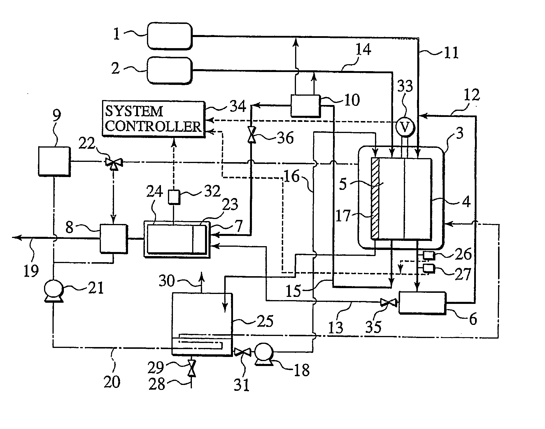
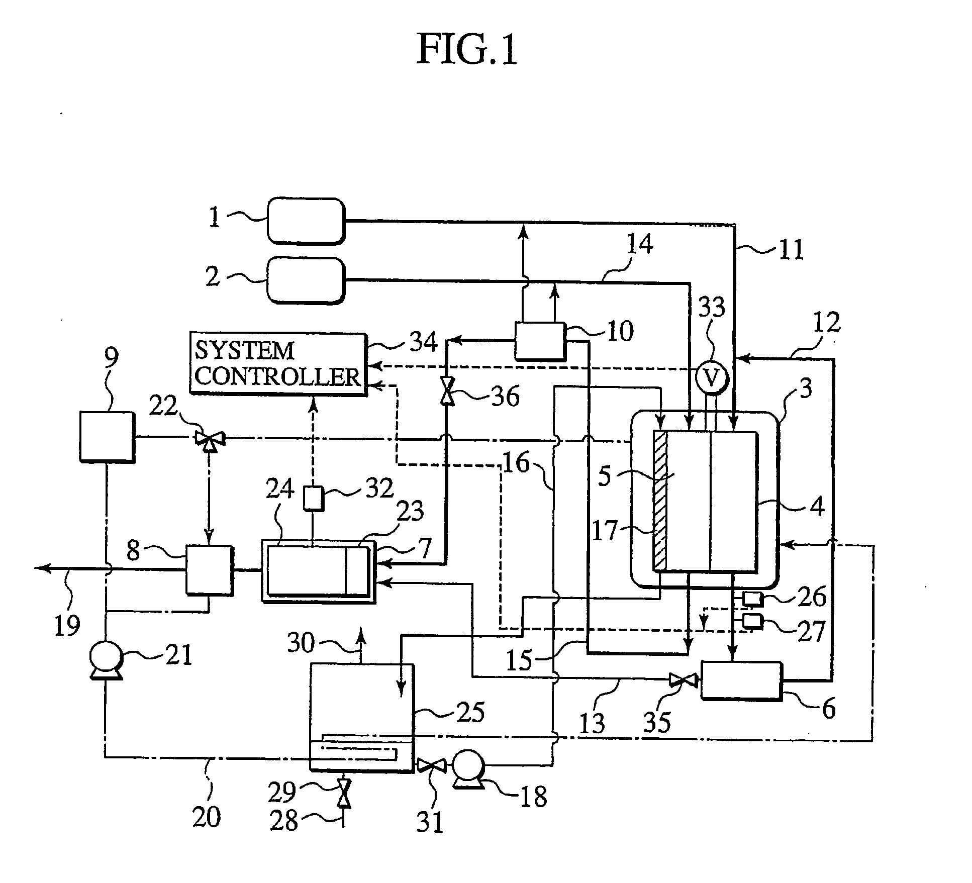
[0016] Referring now to FIG. 1, FIGS. 2A to 2C and FIG. 3, a first embodiment of a fuel cell system according to the present invention is described in detail. FIG. 1 is a structural view of the fuel cell system of the first embodiment.

[0017] In FIG. 1, the fuel cell system of the presently filed embodiment is shown including a hydrogen supply unit (fuel gas supply unit) 1 that supplies hydrogen as fuel gas to an anode 4 of a fuel cell stack 3 through an anode gas supply conduit 11, and an air supply unit (oxidant gas supply unit) 2 that supplies air as oxidant gas to a cathode 5 through a cathode gas supply conduit 14. The fuel cell stack 3 is supplied with hydrogen and air to achieve electrochemical reaction for thereby generating electric power.

[0018] When this takes place, anode off-gas, that is not consumed in the anode 4, is expelled from the anode 4, and cathode off-gas resulting from a portion of oxidant gas consumed in the cathode 5 and containing moisture created through ...

second embodiment

[0044] Next, referring to FIGS. 4A to 4C and FIG. 5, description is made of a fuel cell system of a second embodiment of the present invention. The fuel cell system of the second embodiment is similar in structure to that shown in FIG. 1, with like component parts bearing the same reference numerals for a simplicity of description.

[0045] The fuel cell system of the presently filed embodiment differs from that of the first embodiment in that during the ignition period, no incremental operation for the air flow rate is performed and the system controller (control means) 34 controls in a way to intermittently supply anode off-gas at given time intervals shorter than the ignition time period.

[0046]FIGS. 4A to 4C are timing charts for illustrating how the system controller 34 forming part of the second embodiment controls a hydrogen concentration of mixed gas to be supplied to the catalytic combustor 7, with FIG. 4A representing the concentration of hydrogen supplied to the catalytic c...

third embodiment

[0067] Next, referring to FIGS. 6A to 6C and FIG. 7, description is made of a fuel cell system of a third embodiment of the present invention. The fuel cell system of the third embodiment is similar in structure to that shown in FIG. 1.

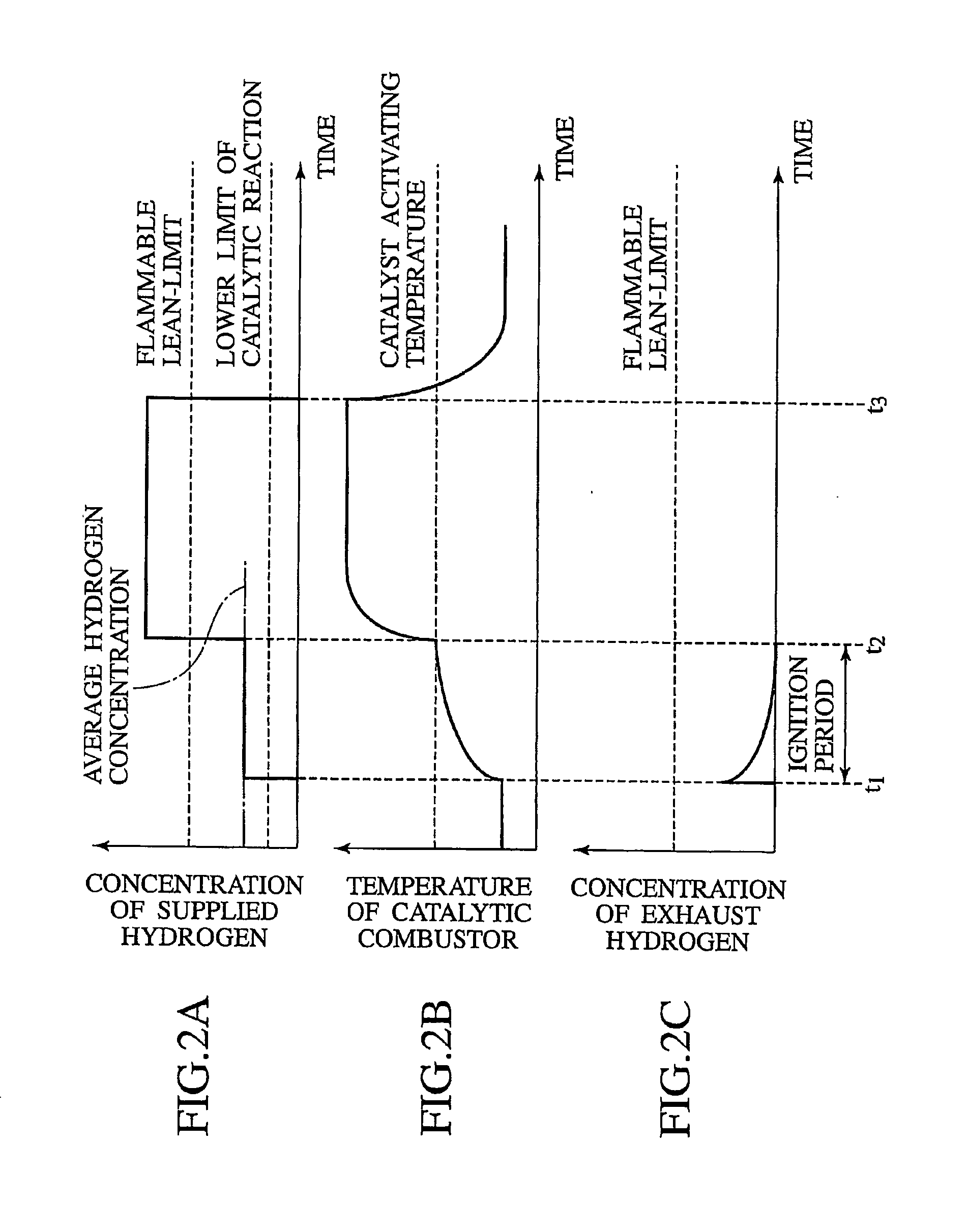
[0068] The fuel cell system of the presently filed embodiment differs from that of the first embodiment in that the flow rate of anode off-gas is increased based on a hydrogen concentration incremental pattern, that is preliminarily obtained for the ignition period, so as to allow the hydrogen concentration in mixed gas to transiently vary from the lower concentration than the flammable lean-limit to the higher concentration than the flammable lean-limit and to allow the average hydrogen concentration during the ignition period to fall in a value above the concentration at which the combustion temperature reaches a value greater than the activating temperature of the catalytic combustor 7 and at the hydrogen concentration (of 4%: here, for instance, ...


PUM

PropertyMeasurementUnit
electric poweraaaaaaaaaa
concentrationaaaaaaaaaa
flow rateaaaaaaaaaa

Abstract

A fuel cell system and related method are disclosed having a catalytic combustor 7 combusting mixed gas between fuel gas, or anode off-gas, and oxidant gas or cathode off-gas, and a system controller 35 operative to perform control such that during at least an ignition period until the catalytic combustor is discriminated to be sufficiently activated from commencement of supplying the mixed gas to the catalytic combustor, a fuel gas concentration of the mixed gas is maintained in a given range (greater than a catalyst activation lower limit and less than flammable lean-limit) whereas after the ignition period has been elapsed, the mixed gas is supplied to the catalytic combustor even if the fuel gas concentration lying at a value deviated from the given range.

Description

TECHNICAL FIELD [0001] This invention relates to fuel cell systems and, more particularly, to a fuel cell system which has an improved combustion characteristic of anode off-gas, and a related method. BACKGROUND ART [0002] A fuel cell system serves to electrochemically react fuel gas, such as hydrogen gas, and oxidant gas containing oxygen to one another to allow an electric energy to be taken out from electrodes disposed on both sides of an electrolyte membrane. Especially, a solid polymer fuel cell employing a solid electrolyte attracts public attention as an electric power supply for an electric vehicle because of a low operating temperature and ease of handling. That is, a fuel cell powered vehicle is an ultimate clean vehicle on which a hydrogen absorbing device, such as a high pressure hydrogen tank, a liquid hydrogen tank and a hydrogen absorbing amorphous alloy tank, is installed to allow hydrogen, supplied from the same, and air including oxygen to be delivered to the fuel ...

Claims


Application Information

Patent Timeline
Patent Type & Authority Applications(United States)
IPC IPC(8): H01M8/00H01M8/10H01M8/04H01M8/06
CPCH01M8/04022Y02E60/50H01M8/0662H01M8/06H01M8/04
Inventor MATOBA, TADASHI
Owner NISSAN MOTOR CO LTD
Why Eureka
Try Eureka