Internal combustion engine

a combustion engine and combustion chamber technology, applied in the direction of machines/engines, electrical control, mechanical equipment, etc., to achieve the effect of suppressing knocking and increasing the temperature of the wall surfa

Active Publication Date: 2017-09-28
TOYOTA JIDOSHA KK
View PDF5 Cites 8 Cited by
  • Summary
  • Abstract
  • Description
  • Claims
  • Application Information

AI Technical Summary

Benefits of technology

[0021]According to the above configuration, even in a high load region in which heat radiation from the internal combustion engine increases, an increase in the temperature of cooling water flowing through the exhaust side of the engine head can be inhibited and thus an increase in the wall surface temperature on the exhaust side of the combustion chamber can be restricted and the occurrence of knocking can be suppressed.
[0022]As described above, according to the internal combustion engine of the present disclosure, by appropriately adjusting the temperature of intake air entering a combustion chamber, an operating region in which operation is performed in the lean mode can be expanded to a high load side while stabilizing combustion in the stoichiometric EGR mode.

Problems solved by technology

However, the conventional technology described above adjusts the intake air temperature according to the load, and none of the various literature described above contains a disclosure or a suggestion with regard to how to favorably adjust the temperature of intake air entering a combustion chamber between operation in the lean mode and operation in the stoichiometric EGR mode.

Method used


Image

  • Internal combustion engine
  • Internal combustion engine
  • Internal combustion engine

Examples


Embodiment Construction

[0031]Embodiments of the present disclosure are described hereunder with reference to the accompanying drawings.

1. Overall Configuration of Internal Combustion Engine

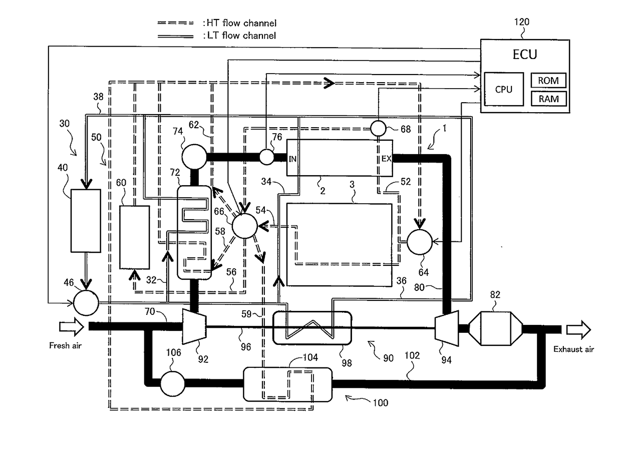
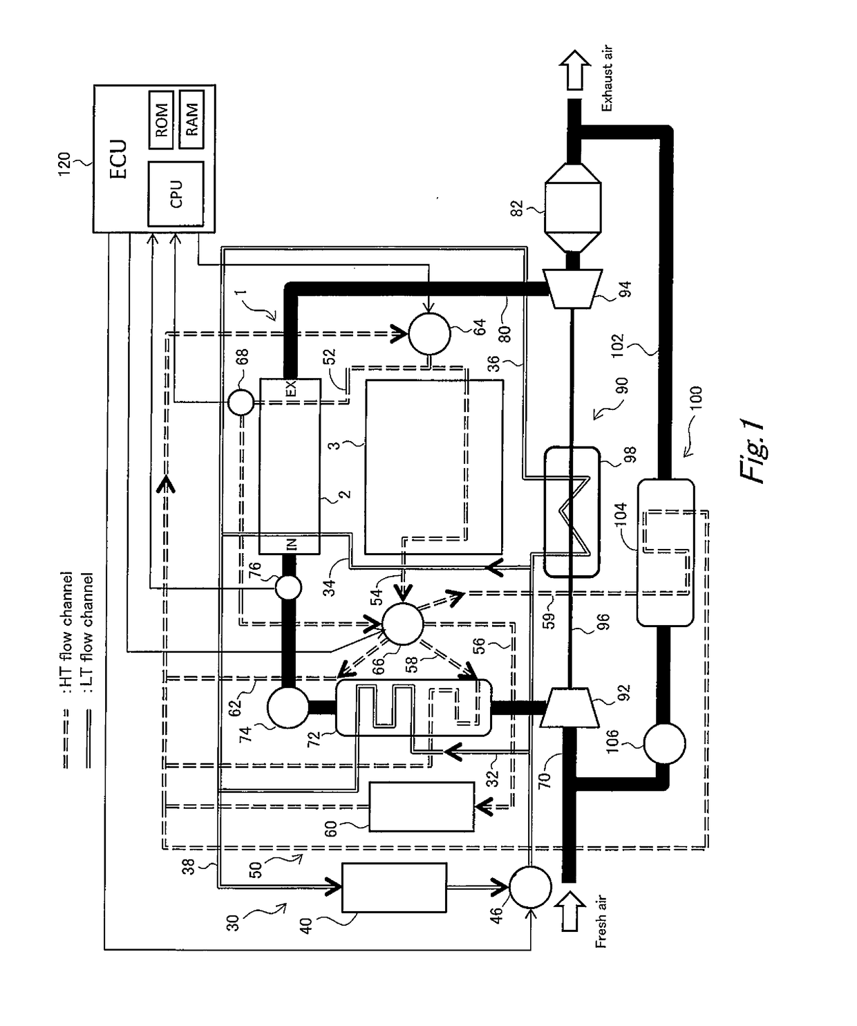
[0032]FIG. 1 is a conceptual diagram illustrating the overall configuration of an internal combustion engine of an embodiment. An internal combustion engine (hereunder, referred to simply as “engine”) 1 includes an engine block 3, and an engine head 2 that is arranged via an unshown gasket on the engine block 3.

[0033]An intake passage 70 and an exhaust passage 80 are connected to the engine head 2. A compressor 92, an intercooler 72 and an electronically controlled throttle 74 are arranged in that order in the intake passage 70 from the upstream side thereof towards the engine head 2. In the intake passage 70 on the downstream side relative to the throttle 74, an intake-air temperature sensor 76 is installed for measuring the temperature of intake air that is introduced into the engine head 2. In the exhaust passage 80,...


PUM


Abstract

An internal combustion engine includes an intake air temperature adjustment apparatus that adjusts the temperature of intake air, and a control apparatus that operates at least the intake air temperature adjustment apparatus. When the internal combustion engine operates in a stoichiometric EGR mode, the control apparatus operates the intake air temperature adjustment apparatus so that the temperature of intake air entering a combustion chamber enters a first temperature region. When the internal combustion engine operates in a lean mode, the control apparatus operates the intake air temperature adjustment apparatus so that the temperature of intake air entering a combustion chamber enters a second temperature region that is a lower temperature region than the first temperature region.

Description

CROSS-REFERENCE TO RELATED APPLICATION[0001]This application is based on and claims the benefit of Japanese Patent Application No. 2016-063502, filed on Mar. 28, 2016, which is incorporated by reference herein in its entirety.BACKGROUND[0002]Field of the Disclosure[0003]The present disclosure relates to an internal combustion engine, and more particularly to an internal combustion engine that, in accordance with an operating region, switches between a stoichiometric EGR mode in which the engine performs operation at the theoretical air-fuel ratio while executing recirculation by means of an EGR apparatus, and a lean mode in which the engine performs operation at an air-fuel ratio that is leaner in fuel than the theoretical air-fuel ratio without performing EGR by means of the EGR apparatus.[0004]Background Art[0005]An internal combustion engine equipped with a supercharger and a water-type intercooler is disclosed in JP 2005-233116 A that, in accordance with an operating region, swi...

Claims


Application Information

Patent Timeline
Patent Type & Authority Applications(United States)
IPC IPC(8): F02B29/04F01P3/18F01P7/16F02M26/17F02D41/00
CPCF02B29/0493F02M26/17F02D41/005F02M26/06F01P3/18F02B29/0425F01P7/16F02D41/0057F02D41/3076F02D41/0002F02D41/0052F02D2200/023F02D2200/0414F02B29/0443F01P7/167F01P2003/024Y02T10/12F01P7/164F01P7/165F01P2003/187F01P2025/32F01P2025/42F01P2060/02
Inventor HOTTA, SHINTAROIRISAWA, YASUYUKITANAKA, HIROYUKINOGAWA, SHINICHIRO
Owner TOYOTA JIDOSHA KK
Why Eureka
Try Eureka