Cross hole deburring tool, cross hole deburring method, and rotary valve machined by using the same

a cross-hole deburring and tool technology, applied in the field of cross-hole deburring tools, cross-hole deburring methods, rotary valves machined, can solve the problems of uniform machined surfaces, difficult deburring machining, and operator injuries, and achieve the effect of improving the mass-productivity of the tool main body, simple structure and uniform surface width

Inactive Publication Date: 2017-10-05
KITZ CORP
View PDF0 Cites 7 Cited by
  • Summary
  • Abstract
  • Description
  • Claims
  • Application Information

AI Technical Summary

Benefits of technology

[0027]From the invention according to claim 1, the shape of the tip part of the cross hole deburring tool is geometrically adapted to the shape of the cross ridgeline part between the inner circumferential surface (spherical surface part) of the spherically-shaped hollow part and the through path in the workpiece. Thus, when deburring machining is performed on the cross ridgeline part by the tool, with rotary cutting by putting the tip part once, finishing can be made to obtain a homogeneous machined surface without asperities and having a substantially uniform surface width over the entire periphery of the machined surface. Also, the tool main body includes the shank and the tip part, and the shape of the tip part has a simple structure with a single shape. Therefore, it is possible to improve mass-productivity of the tool main body and reduce blade manufacturing cost.
[0028]Also, when machining is performed by the cross hole deburring tool of the present invention, at the point of intersection of the inner circumferential surface of the hollow part and the through path in the workpiece, it is possible to form a machined surface so that an angle formed by the tangent of the inner circumferential surface and the tangent of the machined surface (tangent angle) is an obtuse angle. With this, it is possible to suppress an occurrence of a secondary burr by rotary cutting by the deburring tool on the outer periphery of the machined surface after machining.
[0029]From the invention according to claim 2, the shape of the tip part of the cross hole deburring tool is geometrically adapted to the shape of the cross ridgeline part between the inner circumferential surface (cylindrical surface part) of the cylindrically-shaped hollow part and the through path in the workpiece. Thus, when deburring machining is performed on the cross ridgeline part by the tool, with rotary cutting by putting the tip part once, finishing can be made to obtain a homogeneous machined surface without asperities and having a substantially uniform surface width over the entire periphery of the machined surface. Also, the tool main body includes the shank and the tip part, and the shape of the tip part has a simple structure with a single shape. Therefore, it is possible to improve mass-productivity of the tool main body and reduce blade manufacturing cost.
[0031]From the invention according to claim 3, the shape and number of cutting edges and groove parts can be adjusted in accordance with the shape of the workpiece. For example, if a groove part in an appropriate shape is formed at the tip part so that chips can be easily discharged through the groove part to the outside at the time of cutting, an adverse effect on the finished surface due to chips can be suppressed.
[0032]From the invention according to claim 4, even for a cross hole burr of the cross ridgeline part formed on the recessed-shaped spherical surface part or the cylindrical surface part and three-dimensionally distorted, complex operation control is not required, such as continuous fine adjustment of displacement and change in orientation of the tool main body, and deburring machining can be performed with simple operation of only causing the tip part to approach to be put onto the cross ridgeline part. Furthermore, finishing can be made to obtain a homogeneous machined surface without asperities and having a substantially uniform surface width over the entire periphery of the cross ridgeline part.

Problems solved by technology

If a burr remains on the cross ridgeline part, fixing, measuring, and precision machining of the workpiece may be inhibited, thereby bringing various adverse effects such as operator's injury.
This makes the structure, movement locus, and so forth of the blade edge complex, makes deburring machining difficult, and makes a machined surface and so forth after machining nonuniform.
However, as described above, if used with the occurrence of the burr, the seal sliding surface of the seal member is impaired to decrease sealing performance.
Moreover, even if the burr on this cross ridgeline part is subjected to deburring machining by a conventional deburring tool, its machined surface cannot be machined to have a uniform surface width over the entire periphery of the ridgeline.
Therefore, with opening and closing of the valve body, the sliding surface of the seal member is unevenly abraded, causing a decrease of the life of the seal member.
Thus, a seal member with a substantially large diameter with respect to the dimensions of the outflow / inflow port is required, an increase in size of a valve chamber for accommodating the seal member, the valve body, and so forth cannot be avoided, and product cost performance and so forth are degraded.

Method used


Image

  • Cross hole deburring tool, cross hole deburring method, and rotary valve machined by using the same
  • Cross hole deburring tool, cross hole deburring method, and rotary valve machined by using the same
  • Cross hole deburring tool, cross hole deburring method, and rotary valve machined by using the same

Examples


Embodiment Construction

[0051]In the following, preferred embodiments of the cross hole deburring tool, cross hole deburring method, and rotary valve machined by using the same of the present invention are described in detail based on the drawings.

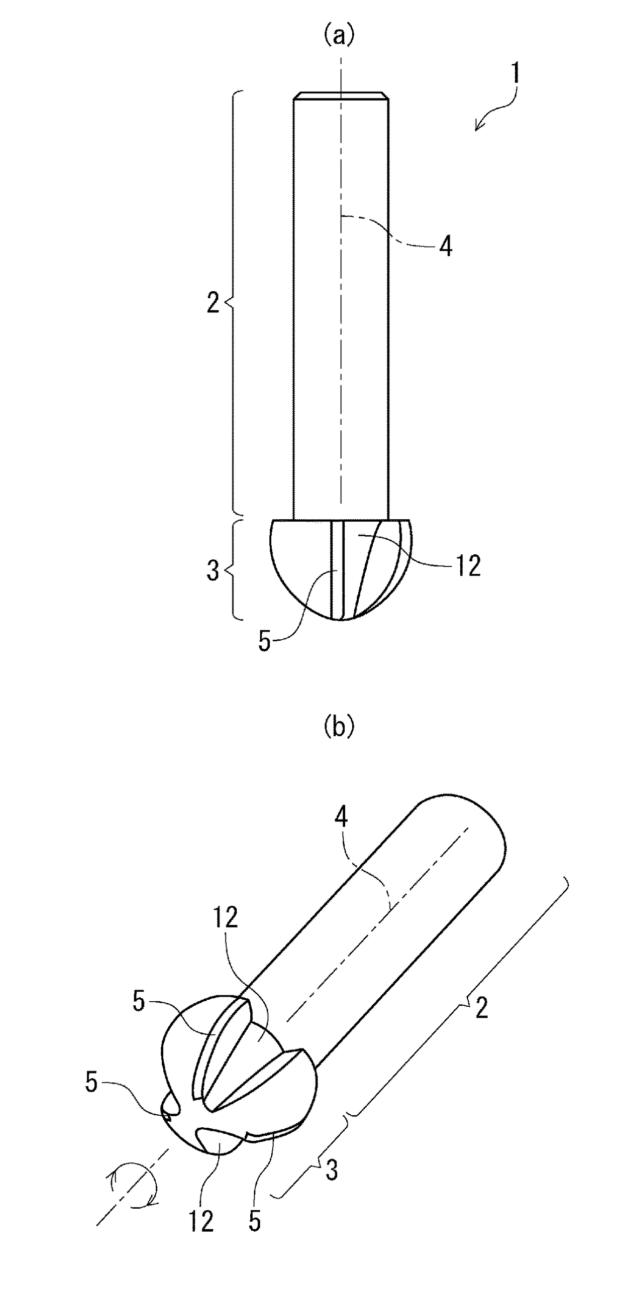
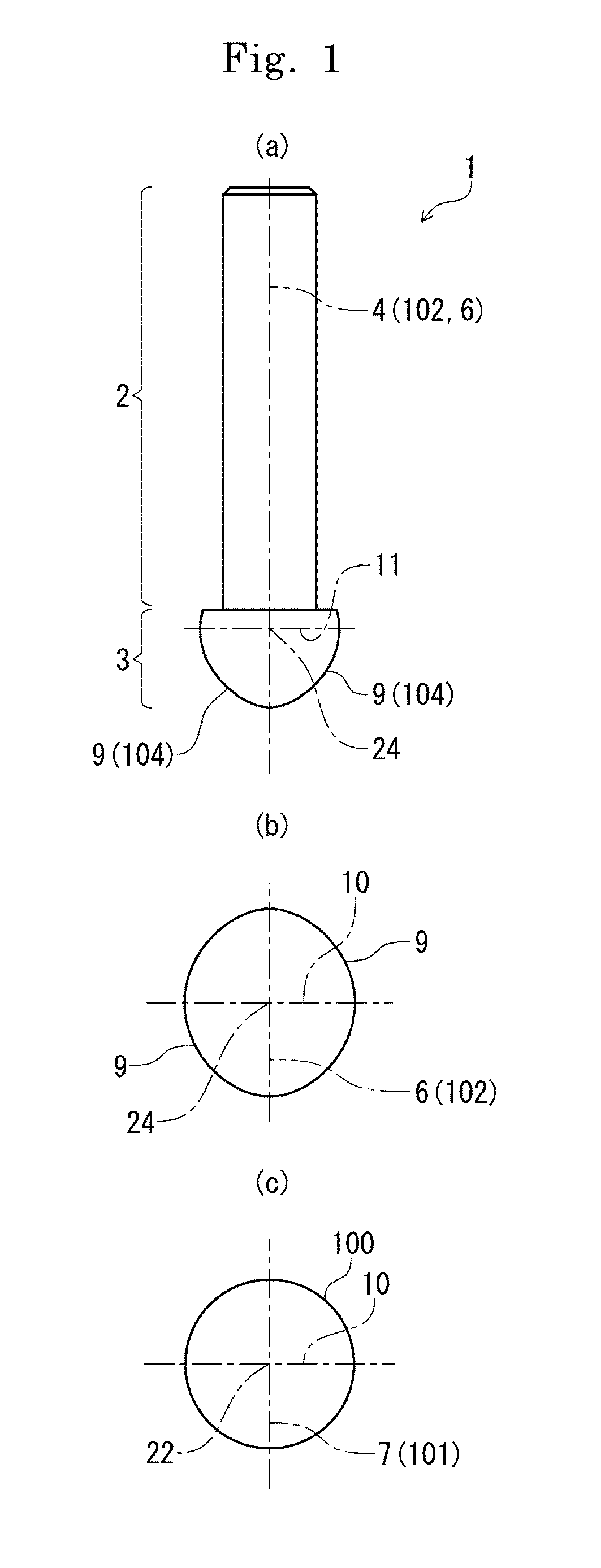
[0052]In FIG. 1, (a) is a side surface outer shape view of a tool main body 1, which is an example of the cross hole deburring tool according to the present invention, (b) is a side surface outer shape view of a bow-shaped solid of revolution depicting the shape of a tip part, and (c) is a side surface outer shape view of a sphere, that is, a perfect circle.

[0053]In FIG. 1(a), the tool main body 1 includes a shank 2 on a cylindrical base end side in an axial direction and a tip part 3 on a tip side in the axial direction for performing rotary cutting. In the drawing, with an upper side as a base end side, the tool is rotatably held to a main shaft of a machine tool or the like by taking a rotation axis 4 as a shaft center, and performs deburring by subjecting a w...


PUM

PropertyMeasurementUnit
diameteraaaaaaaaaa
widthaaaaaaaaaa
shapeaaaaaaaaaa

Abstract

A cross hole deburring tool which performs rotary cutting on a cross hole burr occurring on a cross ridgeline part between a through path and an inner circumferential surface of a spherically-shaped hollow part. A tool main body includes a tip part and a shank, and the tip part has a shape obtained by setting a diameter axis of a circle, setting an eccentric axis parallel to the diameter axis and away therefrom by a predetermined eccentric distance, setting a closed region in a bow shape formed of a line segment obtained by cutting the eccentric axis by the circle and a minor arc on the circle by defining this line segment as a chord, setting an outer surface shape of a bow-shaped solid of revolution formed by rotating this bow shape about the eccentric axis, and taking this outer surface shape as the shape of the tip part.

Description

TECHNICAL FIELD[0001]The present invention relates to, in particular, cross hole deburring tools, cross hole deburring methods, and rotary valves machined by using the same and, in particular, a cross hole deburring tool, cross hole deburring method, and rotary valve machined by using the same capable of cutting and deburring a burr occurring in a cross hole between a cylindrical-shaped through path and a curved inner surface, such as a spherical inner surface or cylindrical inner surface, of a workpiece along its cross ridgeline part into a substantially uniform surface width.BACKGROUND ART[0002]When drilling machining is performed on a workpiece such as a plate material or pipe material by using a cutting tool such as a drill, a material-warping burr occurs on a cross ridgeline part between the workpiece and a machined hole over the entire periphery. If a burr remains on the cross ridgeline part, fixing, measuring, and precision machining of the workpiece may be inhibited, thereby...

Claims


Application Information

Patent Timeline
Patent Type & Authority Applications(United States)
IPC IPC(8): B23B51/10B23B51/08E21B10/60B23K26/361
CPCB23B51/101B23K26/361B23D79/00E21B10/602B23B51/00B23B51/08B23C3/12B23B51/105B23B2265/36B23C2220/20F16K11/0833F16K11/0873
Inventor OHNO, HIROKI
Owner KITZ CORP
Why Eureka
Try Eureka