Manufacturing method for a head slider coated with dlc

Active Publication Date: 2017-10-05
SAE MAGNETICS (HK) LTD
View PDF0 Cites 3 Cited by
  • Summary
  • Abstract
  • Description
  • Claims
  • Application Information

AI Technical Summary

Benefits of technology

[0005]One aspect of the present invention is to provide a manufacturing method for a head slider coated with DLC, thereby the head slider has good film adhe

Problems solved by technology

In this case, when a high bias voltage is applied in order to enhance hardness, the silicon film is mixed with a carbon film, and Si moves toward a surface of the magnetic head, which degrades the wear resistance.
Further, the surface energy of the above overcoat l

Method used


Image

  • Manufacturing method for a head slider coated with dlc
  • Manufacturing method for a head slider coated with dlc
  • Manufacturing method for a head slider coated with dlc

Examples


Embodiment Construction

[0022]Various preferred embodiments of the invention will now be described with reference to the figures, wherein like reference numerals designate similar parts throughout the various views. As indicated above, the invention is directed to a manufacturing method for a head slider coated with DLC, whereby the head slider has good film adhesion performance, higher hardness, better wear resistance, lower surface energy to obtain good hydrophobicity and oleophobicity, and lower fly height in HDD.

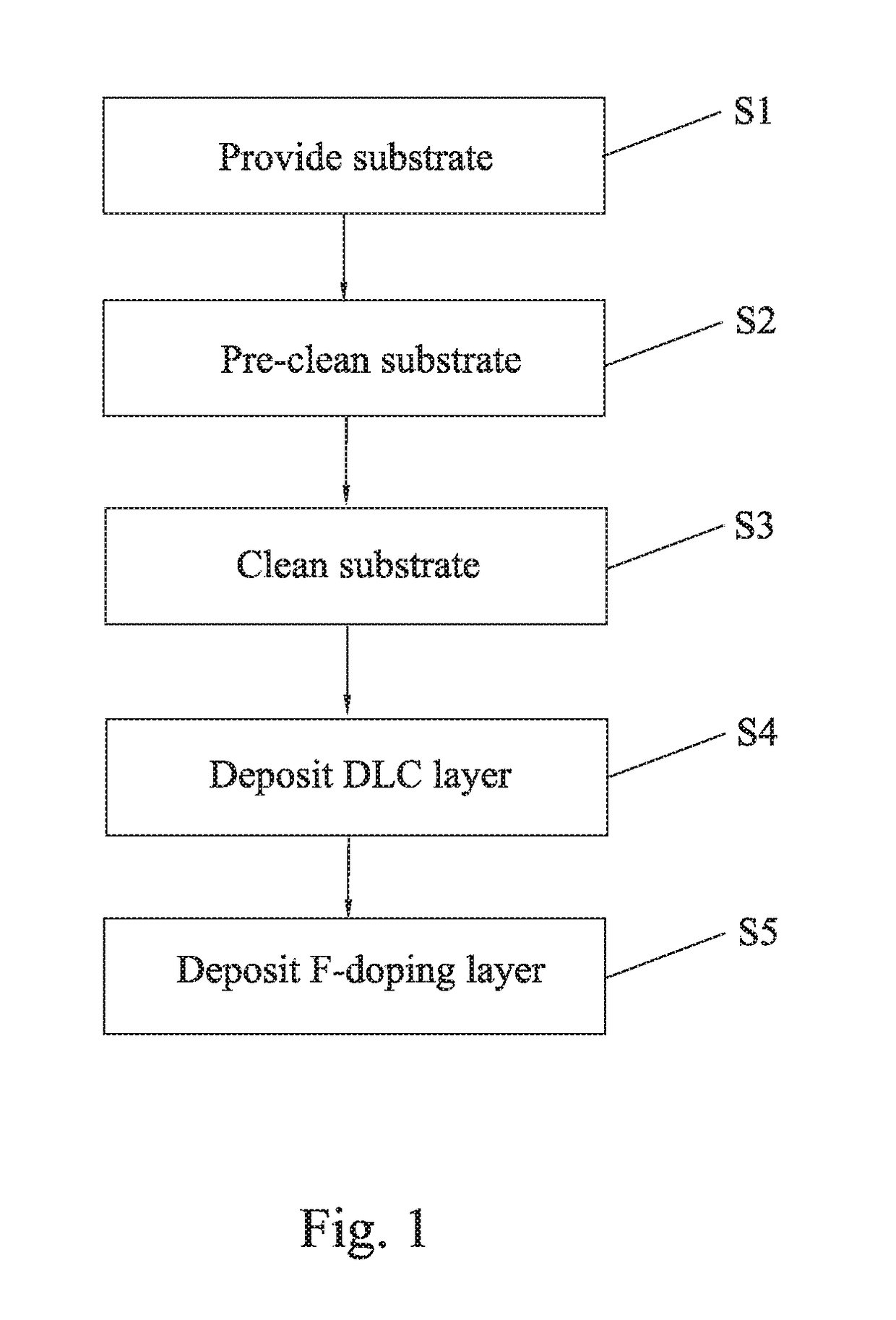
[0023]A manufacturing method for a head slider coated with DLC according to the present invention will be described in detailed by combination with FIGS. 1 to 3. As shown in FIG. 1, the method includes the following steps.

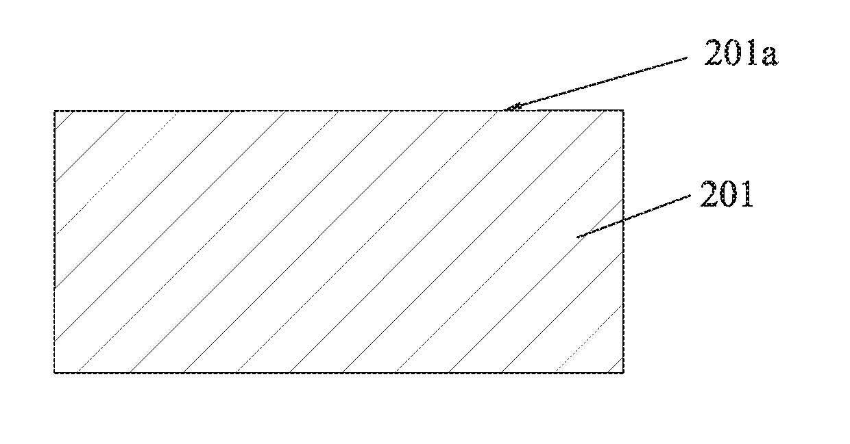
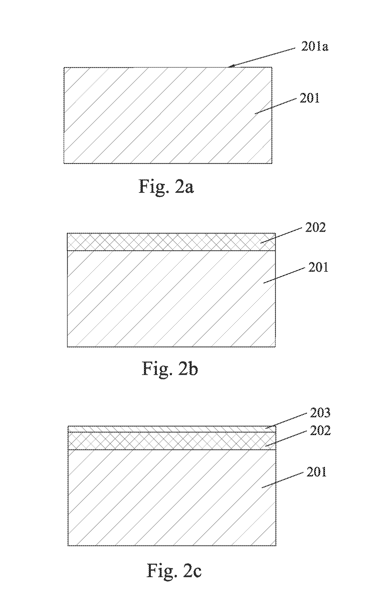
[0024]S1, providing a substrate that is to be finally made into a head slider;

[0025]S2, pre-cleaning the substrate;

[0026]S3, cleaning the substrate;

[0027]S4, depositing a DLC layer on a surface of the substrate, with carbon plasma source being sputtered in a direction that is ...


PUM

PropertyMeasurementUnit
Electric potential / voltageaaaaaaaaaa
Thicknessaaaaaaaaaa
Wear resistanceaaaaaaaaaa

Abstract

A manufacturing method for a head slider coated with Diamond-like Carbon (DLC) includes: providing a substrate that is to be finally made into a head slider; depositing a DLC layer on a surface of the substrate, with carbon plasma source being sputtered in a direction that is vertical to the surface of the substrate; and doping a fluorine-doping (F-doping) layer on the DLC layer. Whereby the head slider has good film adhesion performance, higher hardness, better wear resistance, lower surface energy to obtain good hydrophobicity and oleophobicity, and lower fly height in HDD.

Description

FIELD OF THE INVENTION[0001]The present invention relates to the field of magnetic head manufacturing, and more particularly to a manufacturing method for a head slider coated with diamond-like carbon (DLC) which is used in hard disk drive (HDD).BACKGROUND OF THE INVENTION[0002]As a rule, a protective film for preventing wear is formed on the surface of a magnetic head for use in a hard disk drive or the like (see, e.g. Japanese Application Publication No. 2002-279605). In a technique described in this document, a silicon film is formed on a substrate of the magnetic head by a sputtering process, a DLC film is formed on the silicon film by a CVD process, and a ta-C film is formed on the DLC film by a filtered cathodic vacuum arc (FCVA) process.[0003]Additionally, a silicon film is formed as a contact layer on an air bearing surface (ABS) of the magnetic head, and a protective film is formed on the silicon film by FCVA process in some case. In this case, when a high bias voltage is a...

Claims


Application Information

Patent Timeline
IPC IPC(8): C23C14/34C23C14/58C23C14/06
CPCC23C14/34C23C14/5873C23C14/588C23C14/0611C23C14/022C23C14/0605C23C14/325C23C14/5833G11B5/255G11B5/3106
Inventor HUANG, JIAN HUIDING, XIAO KEMA, HONG TAOFUJII, RYUJIHE, DA YAOFAN, DE JIN
Owner SAE MAGNETICS (HK) LTD
Why Eureka
Try Eureka