Reinforcing member for flexible printed wiring board, and flexible printed wiring board provided with same

a technology of flexible printed wiring board and reinforcement member, which is applied in the direction of flexible printed circuit, circuit bendability/stretchability, printed circuit non-printed electric components association, etc., can solve the problems of increased electric resistance in the conductive state, decreased peeling force of the reinforcing member, etc., and achieves high condition and restraint of electric resistance.

Inactive Publication Date: 2017-10-05
TATSUTA ELECTRICWIRE & CABLE
View PDF12 Cites 10 Cited by
  • Summary
  • Abstract
  • Description
  • Claims
  • Application Information

AI Technical Summary

Benefits of technology

[0019]Increase in an electric resistance is restrained under high-temperature and high-humidity environments, even if the thickness of a surface layer of a reinforcing member is reduced, and hence a ground effect is maintained in a high condition for a long time.

Problems solved by technology
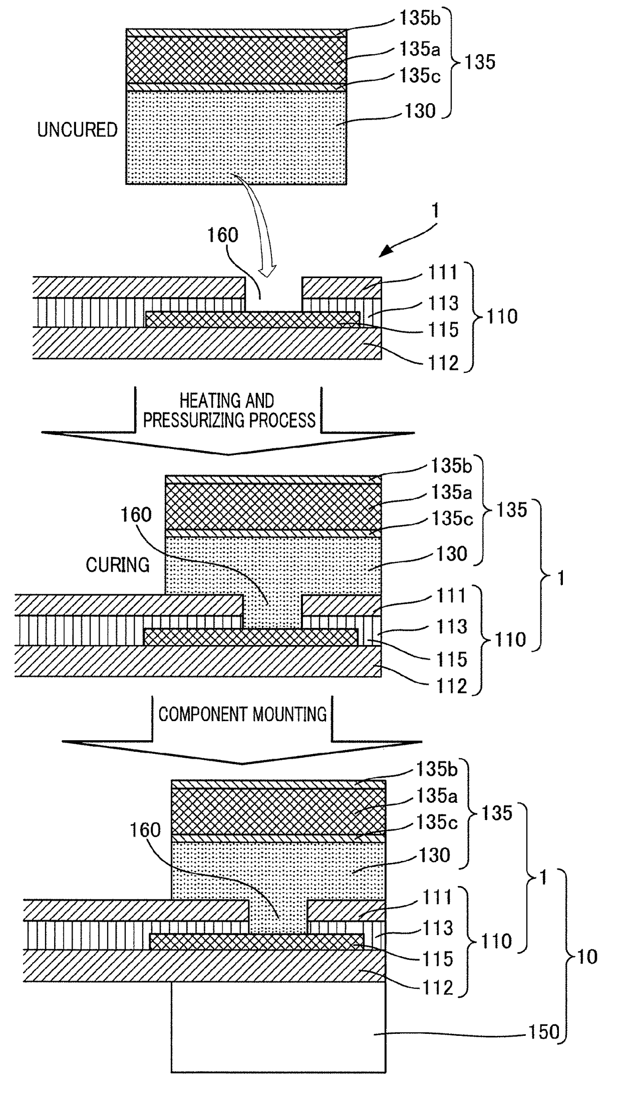
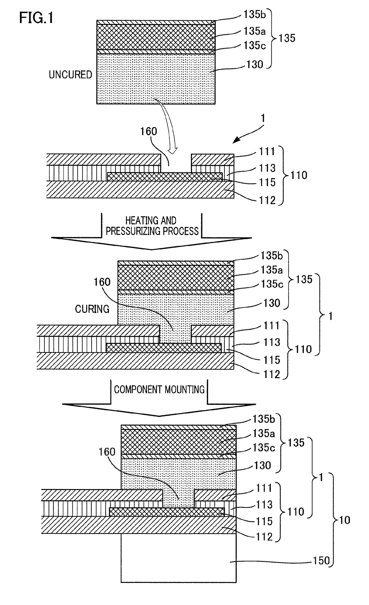
These structures, however, are disadvantageous in that, when the reinforcing member is used in high-temperature and high-humidity environments, a pealing value (i.e., the force required for peeling) of the reinforcing member is decreased with respect to a conductive adhesive, with the result that the electric resistance in the conductive state is increased.

Method used


Image

  • Reinforcing member for flexible printed wiring board, and flexible printed wiring board provided with same
  • Reinforcing member for flexible printed wiring board, and flexible printed wiring board provided with same

Examples


example 1

[0062]When the thickness of the plating was 0.2 μm, the electric resistance, humidity resistance, and comprehensive results were Average when the phosphorus content fell within the range of 2.5 to 22.5%.

examples 2 , 3

Examples 2, 3, and 4

[0063]When the thickness of the plating was 0.3 μm, 0.5 μm, or 0.6 μm, the electric resistance was Good when the phosphorus content fell within the range of 2.5% to 15.0%, the electric resistance was Average when the phosphorus content fell within the range of 18.0% to 20.0%, and the electric resistance was Poor when the phosphorus content was 22.5%.

[0064]In addition to the above, the humidity resistance when the phosphorus content was 2.5% was Poor, the humidity resistance when the phosphorus content fell within the range of 5.0% to 7.0% was Average, and the humidity resistance when the phosphorus content fell within the range of 10.0% to 22.5% was Good.

[0065]Consequently, comprehensive results were Poor when the phosphorus content fell within the range of 2.5% to 22.5%, comprehensive results were Good when the phosphorus content fell within the range of 5.0% to 7.0% or the range of 18.0% to 20.0%, and comprehensive results were Excellent when the phosphorus con...

example 5

[0066]When the thickness of the plating was 0.8 μm, the electric resistance was Good when the phosphorus content fell within the range of 2.5% to 15.0%, the electric resistance was Average when the phosphorus content fell within the range of 18.0% to 20.0%, and the electric resistance was Poor when the phosphorus content was 22.5%.

[0067]In addition to the above, the humidity resistance when the phosphorus content was 2.5% was Poor, the humidity resistance when the phosphorus content fell within the range of 5.0% to 15.0% was Average, and the humidity resistance when the phosphorus content fell within the range of 18.0% to 22.5% was Good.

[0068]Consequently, comprehensive results were Poor when the phosphorus content was 2.5% or lower, comprehensive results were Good when the phosphorus content fell within the range of 5.0% to 20.0%, and comprehensive results were Excellent when the phosphorus content fell was 22.5% or higher.


PUM


Abstract

A reinforcing member for a flexible printed wiring board allows a ground wiring pattern of the flexible printed wiring board to conduct with an external ground potential. The reinforcing member includes a metal base and a nickel layer formed on a surface of the metal base. The nickel layer includes phosphorus in a range from 5.0 percent by mass to 20.0 percent by mass, the rest of the nickel layer is nickel and inevitable impurities, and the nickel layer is 0.2 μm to 0.9 μm thick.

Description

TECHNICAL FIELD[0001]The present invention relates to a reinforcing member for a flexible printed wiring board used in a mobile phone, a computer, or the like, and a flexible printed wiring board including the reinforcing member.BACKGROUND ART[0002]A known flexible printed wiring board is structured such that, in order to prevent an electronic component from dropping off when the wiring board is warped, a reinforcing member is provided on a surface opposite to the surface on which the electronic component is provided, with the result that warpage of the mounting position of the electronic component is prevented by the reinforcing member. Patent Literature 1 and Patent Literature 2 propose structures in each of which a reinforcing member is formed of a metal reinforcing plate and a ground circuit of a flexible printed wiring board is connected to a housing in a conductive state via the metal reinforcing plate.[0003]These structures, however, are disadvantageous in that, when the rein...

Claims


Application Information

Patent Timeline
Patent Type & Authority Applications(United States)
IPC IPC(8): H05K1/02H05K1/18H05K3/32H05K1/09
CPCH05K1/0281H05K1/0215H05K1/0218H05K1/09H05K2201/0715H05K3/321H05K2201/2009H05K2201/1028H05K1/189H05K2201/09136H05K2201/05
Inventor TAJIMA, HIROSHIWATANABE, MASAHIRO
Owner TATSUTA ELECTRICWIRE & CABLE
Why Eureka
Try Eureka