Systems and methods for payload integration and control in a multi-mode unmanned vehicle

a multi-mode, unmanned vehicle technology, applied in special-purpose vessels, aircraft convertible vehicles, instruments, etc., can solve the problems of limiting the range of unmanned vehicle characteristics, limiting the scope of conventional unmanned vehicle designs, and limiting the operational and performance envelope of vehicles designed for carrying people, so as to facilitate the execution of more complex missions, enhance vehicle utility, and enhance operational characteristics

Active Publication Date: 2017-10-19
UNMANNED INNOVATION
View PDF0 Cites 35 Cited by
  • Summary
  • Abstract
  • Description
  • Claims
  • Application Information

AI Technical Summary

Benefits of technology

[0017]With the foregoing in mind, one of the many objects of the present invention is to provide advantageously and readily-deployable systems and methods for mission planning and control of an unmanned vehicle with enhanced operational characteristics in multiple modes, that is, on the surface of water, underwater, and in the air. These enhanced operational characteristics include, but are not limited to, speed, maneuverability, sea state handling, endurance, stealth, payload capacity, sensory capability, communication ability, and operational autonomy. It is further an object of the present invention to provide systems and methods for mission planning and control of unmanned vehicles with endurance characteristics that enable them to autonomously operate for weeks, months, and years without human intervention. It is further an object of the present invention to provide systems and methods for mission planning and control of unmanned vehicles in a range of sizes that include, but are not limited to, unmanned vehicles small and light enough for a single person to carry, larger unmanned vehicles that can fit in standard maritime containers, and unmanned vehicles as large as current manned ships. It is further an object of the present invention to provide systems and methods for mission planning and control systems that include off board command, control and communication systems that enable people to interact with the unmanned vehicles in ways that advantageously exploit various degrees of autonomy and time synchronization. It is further an object of the present invention to provide systems and methods for mission planning and control of unmanned vehicles that can communicate through a variety of means with an integrated off board system to facilitate execution of more complex missions over larger maritime areas with fewer human operators. It is further an object of the present invention to provide systems and methods for mission planning and control that include a set of off-board command, control and management systems to plan, execute and manage a fleet of unmanned vehicles across a number of missions and a set of systems physically distinct from the unmanned vehicle that increase vehicle utility. It is further an object of the present invention to provide systems and methods to plan, program, execute, and monitor missions with autonomous maritime vehicles in multi-mode operation including, but not limited to, transit routes, navigation, sea state handling, perception and obstacle avoidance, sensor control and communication, and contingency operation based on sensor inputs and data processing.
[0025]The systems and methods for mission planning and control of the unmanned vehicle may include control surface systems that may include a rudder, trim plates, forward canards, and control position sensors used to maneuver the unmanned vehicle. The rudder may be mounted on a strut that may be affixed externally to the vehicle body and substantially near the stern of the vehicle body. Trim plates may be affixed externally to the vehicle body and may articulate independently and bi-directionally. Forward canards may be affixed externally to the vehicle body and may articulate independently in two directions to achieve maximum roll of the unmanned vehicle. Control position sensors may monitor the position of the rudder, the trim plates, and the forward canards to support physical maneuvering of the unmanned vehicle on land, in the air, on the surface of the water, and below the surface of the water.
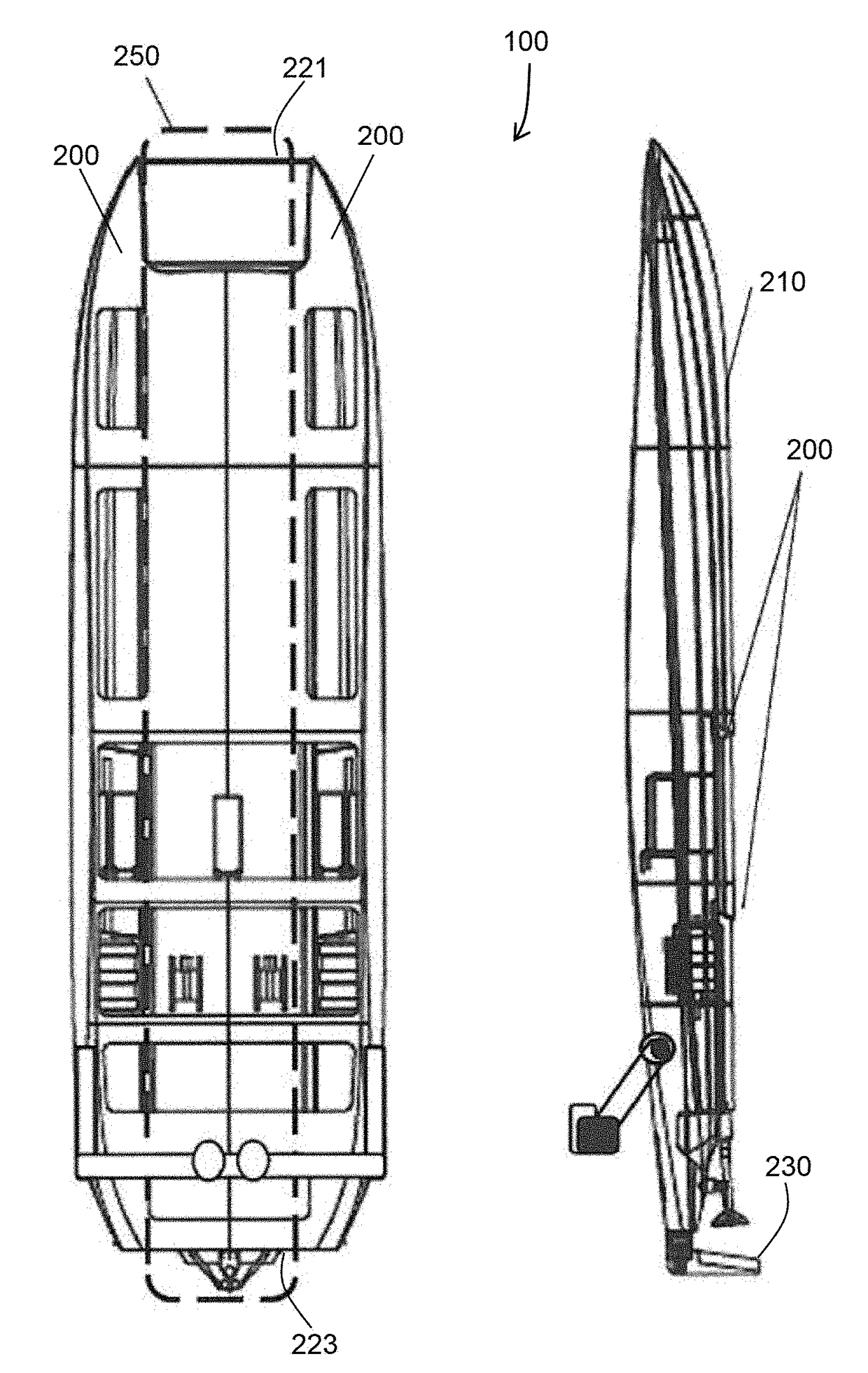
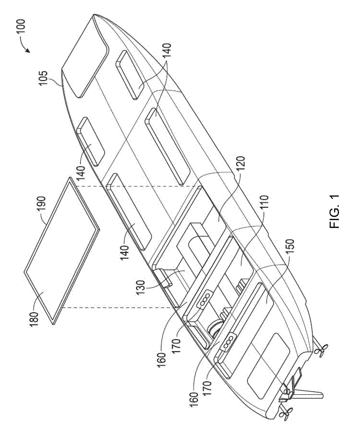
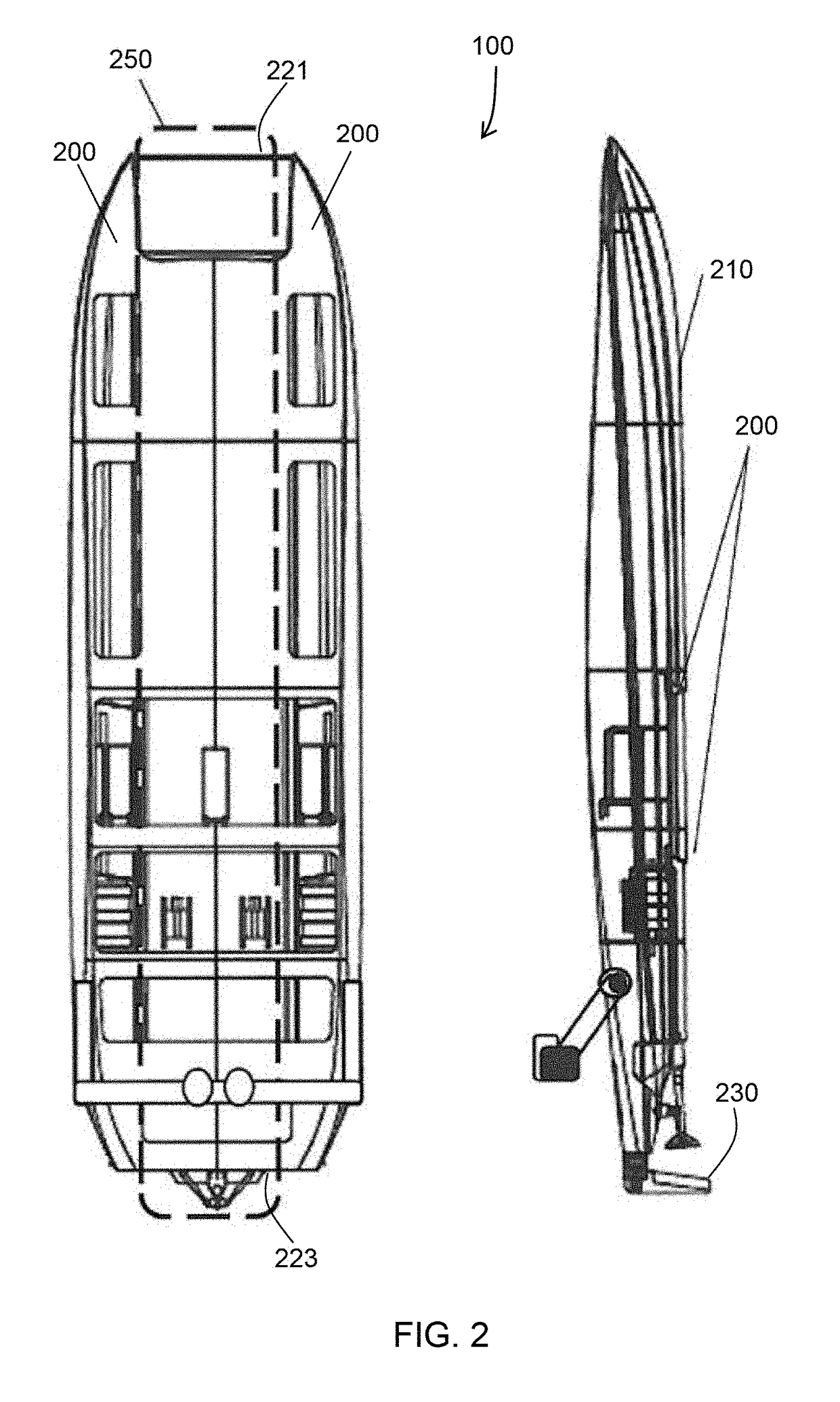
[0027]The systems and methods for mission planning and control of the unmanned vehicle may include a payload deck system that may provide mechanical, power, and signal mount points for payload modules that may interchangeably affix to the vehicle body of the unmanned vehicle. The payload deck system may present a universal mounting interface for diverse payload modules that can expand the operational characteristics and mission capabilities of the unmanned vehicle.

Problems solved by technology

Conventional unmanned vehicle designs typically are each limited in scope to a particular operating environment and / or beneficial task.
In the marine and submarine environments, most current unmanned vehicle designs are based on retrofits of manned vehicle designs and, as result, incur operational and performance envelope limitations built into vehicles designed for carrying people, such as described in U.S. Pat. No. 7,789,723 to Dane et. al.
However, these designs typically preclude achievement of a broader range of unmanned vehicle characteristics (e.g., multi-environment, multi-task) for the sake of limited-environment limited-task characteristics.
(b) Varying integration requirements cause time consuming individual work for each sensor;
(c) Sensors are often not rugged enough to withstand the multi-mode environment;
In addition to the limitations inherent to vehicle design, challenges exist in design of command and control systems required to effectively operate both individual unmanned systems and also groups of such systems operating cooperatively toward accomplishment of a common objective.
However, limitations in the capabilities of the unmanned vehicles being controlled by conventional command and control systems often limit the problems that may be solved using those systems.
More specifically, no existing system accounts for controlled unmanned vehicles that are each capable of selective operation in air, on the surface of water, and underwater.

Method used


Image

  • Systems and methods for payload integration and control in a multi-mode unmanned vehicle
  • Systems and methods for payload integration and control in a multi-mode unmanned vehicle
  • Systems and methods for payload integration and control in a multi-mode unmanned vehicle

Examples


Embodiment Construction

[0065]The present invention will now be described more fully hereinafter with reference to the accompanying drawings. In which preferred embodiments of the invention are shown. This invention may, however, be embodied in many different forms and should not be construed as limited to the embodiments set forth herein. Rather, these embodiments are provided so that this disclosure will be thorough and complete, and will fully convey the scope of the invention to those skilled in the art. Those of ordinary skill in the art realize that the following descriptions of the embodiments of the present invention are illustrative and are not intended to be limiting in any way. Other embodiments of the present invention will readily suggest themselves to such skilled persons having the benefit of this disclosure. Like numbers refer to like elements throughout.

[0066]In this detailed description of the present invention, a person skilled in the art should note that directional terms, such as “abov...


PUM


Abstract

Systems and associated methods for rapid integration and control of payloads carded by a multi-mode, unmanned vehicle configured to accommodate a variety of payloads of varying size, shape, and interface and control characteristics. Mechanical, power, signal, and logical interfaces to a variety of payloads operate to enable environmental protection, efficient placement and connection to the vehicle, and control of those payloads in multiple environmental modes as well as operational modes (including in air, on the surface of water surface, and underwater).

Description

RELATED APPLICATIONS[0001]This application is a continuation-in-part and claims the benefit under 35 U.S.C, §120 of U.S. patent application Ser. No. 14 / 788,231 filed by the inventor of the present application on Jun. 30, 2015, and titled SYSTEMS AND METHODS FOR MULTI-MODE UNMANNED VEHICLE MISSION PLANNING AND CONTROL which, in turn, is a continuation-in-part and claims the benefit under 35 U.S.C. §120 of U.S. patent application Ser. No. 13 / 470,866 (now U.S. Pat. No. 9,096,106) titled MULTI-ROLE UNMANNED VEHICLE SYSTEM AND ASSOCIATED METHODS filed on May 14, 2012, which, in turn, claims the benefit under 35 U.S.C. §119(e) of U.S. Provisional Patent Application Ser. No. 61 / 485,477 titled MARITIME MULTI-ROLE UNMANNED VEHICLE SYSTEM filed on May 12, 2011, the entire contents of each of which are incorporated herein by reference except to the extent that the contents therein conflict with the contents herein.FIELD OF THE INVENTION[0002]The present invention relates generally to the field...

Claims


Application Information

Patent Timeline
Patent Type & Authority Applications(United States)
IPC IPC(8): G05D1/00B64C3/38B63G8/22B63B1/32B63B1/04B64C39/02B60F5/02
CPCG05D1/0088B60F5/02B63B1/322B64C3/38B63G8/22B63B1/042B64C39/024B60F5/00B63B1/32B63G8/26B64C35/00B63B2001/206B63B2035/006B63B2035/007B63B2035/008B63G2008/004B64C37/00B63B2001/186B63B2209/18B63H21/21B63H9/061Y02T70/10Y02T70/5236B64U10/25B64U10/00B64U2101/00B64U2201/10B64U2201/20
Inventor HANSON, BRUCE BECKERHANSON, THOMAS EDWARD
Owner UNMANNED INNOVATION
Why Eureka
Try Eureka