
Mobile medicine communication platform and methods and uses thereof

a mobile medicine and communication platform technology, applied in the field of mobile telemedicine, can solve the problems of not being able to find the appropriate hospital equipped to treat stroke patients, not receiving medical attention for many stroke victims, and the situation will only become more desperate, so as to reduce the resending of packets, increase the resiliency of telemedicine sessions, and reduce packet loss

Active Publication Date: 2017-10-19
BR INVENTION HLDG LLC
View PDF8 Cites 108 Cited by
  • Summary
  • Abstract
  • Description
  • Claims
  • Application Information

AI Technical Summary

Benefits of technology

The patent text describes a telemedicine system that can communicate with a remote operations center and medical facilities using wireless communication protocols. The system uses a Transport Morphing Protocol (TMP) to establish a secure and reliable session with the operations center and medical facilities, and to mask any temporary network degradations. The controller can adjust data send rate and switch between satellite communication and cellular communication to ensure optimal communication. The system can also use molecular analysis to improve the precision of diagnosis. Additionally, the system includes an enhanced transport layer to optimize transmission across different networks. Overall, the telemedicine system provides real-time communication and increases the efficiency and accuracy of medical diagnosis.

Problems solved by technology

Moreover, stroke is the leading cause of disability in the United States and the rest of the world.
With an aging US population, the situation will only become more desperate.
However, many individuals suffering a stroke do not receive medical attention in time or are not diagnosed with a stroke.
In some instances, patients are rushed to the closest hospital, but not the appropriate hospital equipped for treating a stroke patient.
A hospital may be inappropriate because of inadequate diagnostic equipment, or lack of immediate access to required diagnostic and imaging testing.
Also, the hospital may lack medical professionals, such as neurologists or interventional vascular specialists who are trained to give expert interpretation and necessary and warranted therapies.
By the time the patient is diagnosed with a stroke, it may be discovered that the patient is at the wrong hospital and the potential for long term affects increases.
A golden hour from stroke onset to therapy in selected strokes, particularly those involving the large vessels is recommended, but blood thinner therapy up until 4.5 hours and clot removal up until 6-8 hours but with diminished efficacy of the treatment after the first hour.
These strokes have the highest potential for significant morbidity and mortality.
In some instances, definitive therapy may not be available because the stroke has already occurred or is too large and cannot be reversed.
Despite national protocols for stroke care with improved prognosis, the process and logistics of patient care from time of onset (T1) of Stroke or traumatic brain injury (TBI) Episode through initial hospital encounter and emergent and acute care during the acute episode (T ‘n’) in the Emergency Department is inconsistent nationwide.
Disorders that are not stroke may not be identified, but still receive potentially dangerous therapy for stroke.
Thus, optimal, personalized care is not being done.
Hence, there may be delivery of patients to inappropriate sites, unsafe / unwarranted treatment, delayed treatment, inability to treat due to time limitations, increased brain damage, and poorer prognosis.
If the patient arrives late, or is seen outside of the acceptable time window, or the patient has too many other medical risk factors to allow definitive therapy, then these factors may lead to complications, including brain hemorrhage.
Also, screening of patients with stroke causing conditions is often not done.

Method used


Image

  • Mobile medicine communication platform and methods and uses thereof
  • Mobile medicine communication platform and methods and uses thereof
  • Mobile medicine communication platform and methods and uses thereof

Examples


Embodiment Construction

[0056]In the following description, numerous specific details are set forth in order to provide a thorough understanding of the aspects of the present disclosure. However, it will be apparent to those skilled in the art that the aspects, including structures, systems, and methods, may be practiced without these specific details. The description and representation herein are the common means used by those experienced or skilled in the art to most effectively convey the substance of their work to others skilled in the art. In other instances, well-known methods, procedures, components, and circuitry have not been described in detail to avoid unnecessarily obscuring aspects of the disclosure.

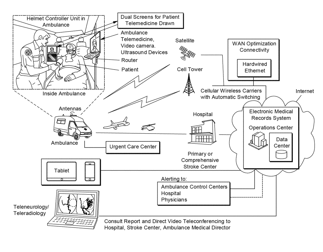
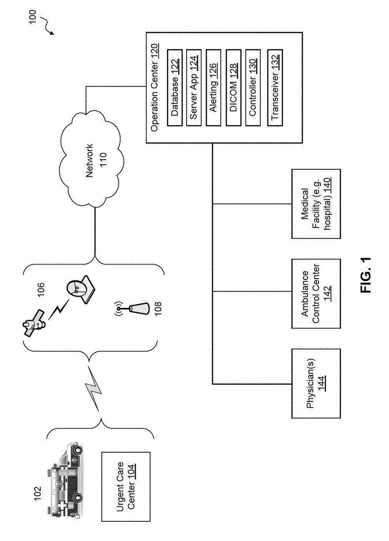
[0057]As an overview, the present disclosure provides a systems and methods for assessing a patient for one or more traumatic brain injuries, such as for a stroke, and other neurological disorders while in transport in an emergency vehicle, such as an ambulance, emergency helicopter, airplane, trai...


PUM


Abstract

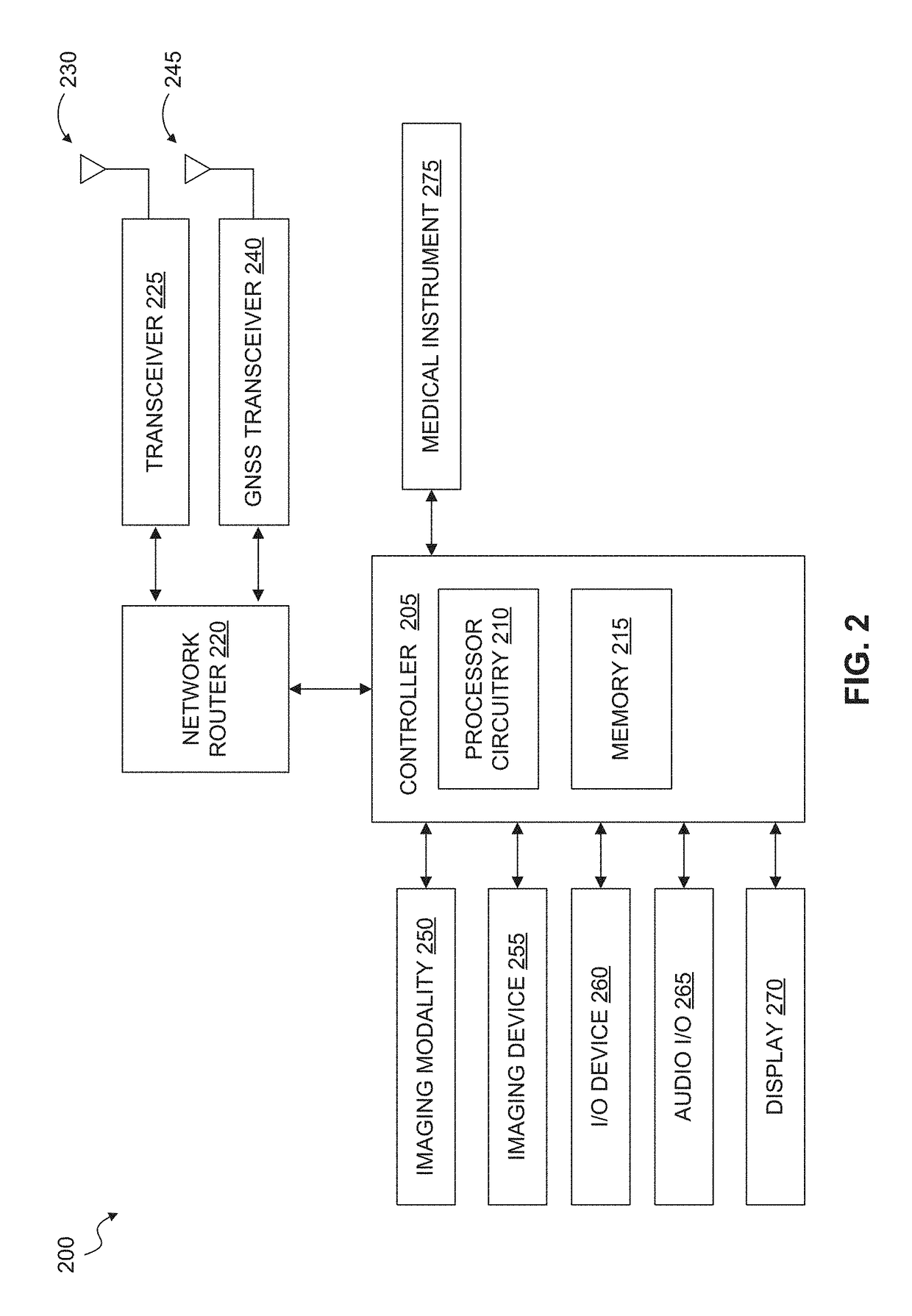
Telemedicine systems and methods are described. In a telemedicine system operable to communicate with a remote operations center, communications can be transmitted / received using a transceiver having an antenna. The antenna can include first and second di-pole antenna elements, the first di-pole antenna element being vertically polarized and the second di-pole antenna element being horizontally polarized. A controller of the system can establish, using the transceiver, a telemedicine session with the operations center using a Transport Morphing Protocol (TMP), the TMP being an acknowledgement-based user datagram protocol. The controller can also mask one or more transient network degradations to increase resiliency of the telemedicine session. The telemedicine system can include a 2D and 3D carotid Doppler and transcranial Doppler and / or other diagnostic devices, and provides for real-time connectivity and communication between medical personnel in an emergency vehicle and a receiving hospital for immediate diagnosis and treatment to a patient in need.

Description

CROSS REFERENCE TO RELATED APPLICATIONS[0001]This application claims priority to and the benefit of U.S. Provisional Application No. 62 / 323,005, filed on Apr. 15, 2016, which is hereby incorporated by reference.[0002]This application also discloses products and references, such as (A) PCT Application No. PCT / US2013 / 067713, which was filed on Oct. 31, 2013 and entitled “Novel System for Emboli Detection in the Brain Using a Transcranial Doppler Photoacoustic Device Capable of Vasculature and Perfusion Measurement;” (B) U.S. patent application Ser. No. 14 / 674,411, which was filed on Mar. 31, 2015 and entitled “Helmet Apparatus and System with Carotid Collar Means On-Boarded;” (C) U.S. patent application Ser. No. 14 / 070,264, filed on Nov. 1, 2013 and entitled “Emboli detection in the brain using a transcranial Doppler photoacoustic device capable of vasculature and perfusion measurement;” (D) U.S. patent application Ser. No. 14 / 084,039, which was filed on Nov. 19, 2013 and entitled “Me...

Claims


Application Information

Patent Timeline
IPC IPC(8): G06F19/00H04L29/06H04B7/185H01Q5/28H01Q9/16H01Q1/32H04W28/06H04L29/08H04L69/40
CPCG06F19/3418H04L67/12H04W28/06H01Q1/3275H04B7/18528H01Q5/28H01Q9/16H04L69/08H01Q1/1214H01Q1/42H01Q9/0407H01Q9/28H01Q21/24H01Q21/26H01Q21/28H04L1/00H04L69/40A61B5/0022A61B5/024G16H40/67G16H40/63
Inventor STEIN, STUART ALANSMITH, CRAIG STEVEN
Owner BR INVENTION HLDG LLC
Learn More