
Flexible snap-fit prosthetic component

a prosthetic component and flexible technology, applied in the field of prosthetic components and surgical methods for artificial joint replacement, can solve the problems of metal erosion, bone resorption, bone loss,

Active Publication Date: 2017-10-26
HOWMEDICA OSTEONICS CORP
View PDF3 Cites 3 Cited by
  • Summary
  • Abstract
  • Description
  • Claims
  • Application Information

AI Technical Summary

Benefits of technology

The present invention provides flexible prosthetic components with outer articular surfaces and bone contacting surfaces that have one or more protrusions extending outwardly. These components can be easily slipped over and snap-fit around resected bone using a snap-fit method, eliminating or reducing the need for bone cement. The interlocking fit between protrusions and recesses in resected bone results in secure mechanical retention, reducing stress on the bone. The flexible polymers used in making the components are more flexible and biocompatible than metallic components, reducing complications and leading to less bone resorption. These components can reduce bone stress shielding and lead to less bone resorption. The patent also describes an embodiment where the bone contacting surfaces are parallel to each other and perpendicular to a distal surface, and angled protrusions ratchet into corresponding recesses in the bone. This strengthens the interlocking of the flexible prosthetic to resected bone.

Problems solved by technology

After implantation, the friction these components are subjected to may lead to metal erosion.
Metal ions and debris released at the area of the implant can lead to complications such as osteolysis.
Build-up of metal debris in soft body tissue can cause metallosis.
Clinical patient series and animal experiments have shown that reduce stress loading can lead to bone loss.

Method used


Image

  • Flexible snap-fit prosthetic component
  • Flexible snap-fit prosthetic component
  • Flexible snap-fit prosthetic component

Examples


Embodiment Construction

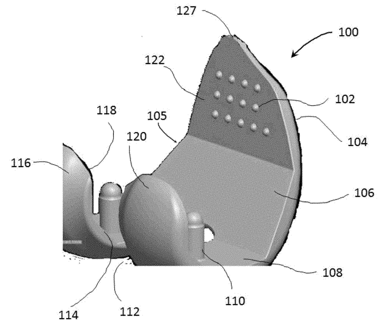
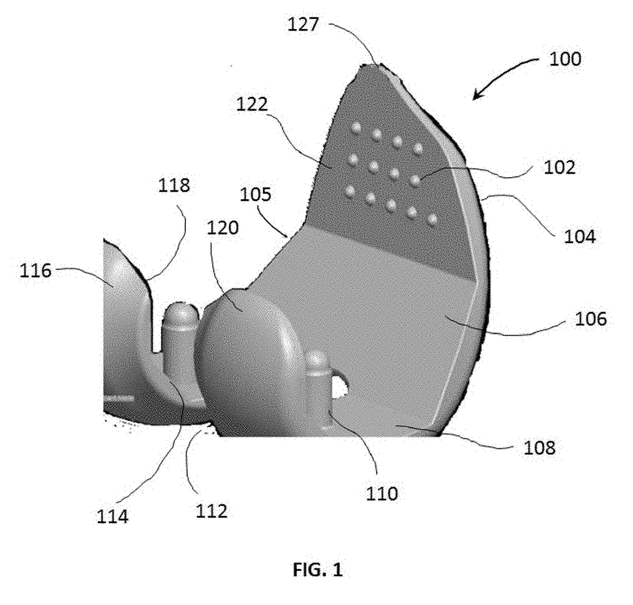
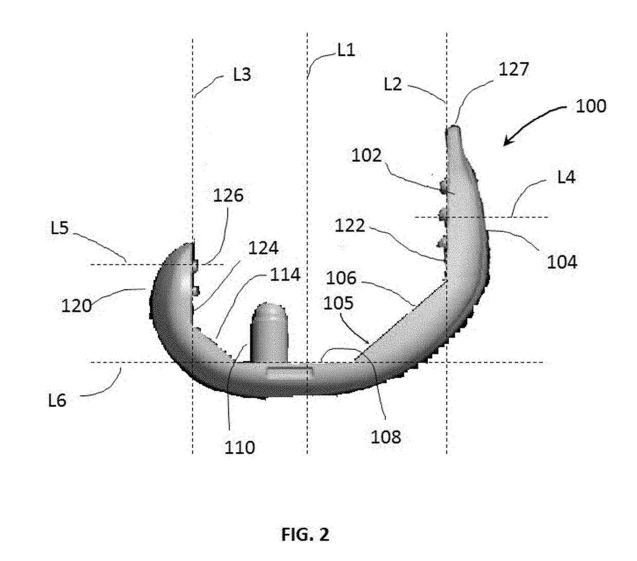
[0028]Referring to FIGS. 1-3, there is shown an embodiment of a flexible prosthetic component depicting a distal femoral component 100. Femoral component 100 has an outer articular surface 104 and an opposing inner bone contacting surface 105. Outer articular surface 104 includes an articular condyle surface having a pair of laterally spaced-apart articular posterior condyle surfaces. The outer articular surface is curved to correspond to the convex curvature of a femoral condyle prior to any degeneration or wear thereof. An articular posterior medial condyle surface 116 and an articular posterior lateral condyle surface 120 are separated by a cut-out for the intercondylar notch 112.

[0029]The inner bone contacting surface 105 opposing the outer articular surface 104 comprises an anterior surface 122, an anterior chamfer surface 106, a distal surface 108, a posterior chamfer surface 114, a posterior medial condyle surface 118, and a posterior lateral condyle surface 124. A longitudin...


PUM


Abstract

Disclosed herein are flexible prosthetic components that are designed to be snap-fit to bone of a patient. The prosthetic components each have an outer articular surface and an inner bone contacting surface opposing the outer articular surface. The bone contacting surface has an anterior surface and an opposing posterior surface configured to contact corresponding anterior and posterior surfaces of the patient's bone. At least one of the anterior and posterior surfaces includes one or more protrusions extending outwardly therefrom. The anterior and posterior surfaces of the prosthetic components may flex toward and away from one another such that the one or more protrusions may snap-fit into corresponding recesses in the bone. The bone of the patient may be resected to include planar surfaces or resurfaced to include a curved surface corresponding to the respective bone contacting surface of the prosthetic components.

Description

FIELD OF THE INVENTION[0001]The present invention relates to prosthetic components and surgical methods for artificial joint replacement, and in particular relates to flexible prosthetic components that can be snap-fit onto resected bone.BACKGROUND OF THE INVENTION[0002]Joint replacement surgery to remove and replace arthritic or dysfunctional joint surfaces with orthopedic prosthesis is widespread today. Hip and knee replacement operations are among the most commonly performed operations in the U.S. Knee replacement surgery can involve one or more damaged knee surfaces. Total knee arthroplasty (“TKA”) is used to treat various forms of knee arthropathies, and is performed by removing and replacing all damaged articulating surfaces of the knee with a prosthetic component. Generally, TKA includes one or more of the following steps: a) removal of damaged cartilage along with a small amount of bone from the tibia and femur, b) replacement of damaged bone surfaces with metal components, ...

Claims


Application Information

Patent Timeline
IPC IPC(8): A61F2/30A61F2/36A61F2/32A61F2/38
CPCA61F2/30767A61F2/36A61F2230/0093A61F2/38A61F2/32A61F2/3859
Inventor HANSON, KEENAN
Owner HOWMEDICA OSTEONICS CORP
Learn More