Supercharge Your Innovation With Domain-Expert AI Agents!

Effusion cells, deposition systems including effusion cells, and related methods

Active Publication Date: 2017-10-26
INNOVATIVE ADVANCED MATERIALS INC
View PDF0 Cites 2 Cited by
  • Summary
  • Abstract
  • Description
  • Claims
  • Application Information

AI Technical Summary

Benefits of technology

The present disclosure provides effusion cells that have a reduction in cost compared to previous designs. These cells can be made using high purity, widely available materials instead of expensive rare metals. The cells do not include any resistive heating filaments or heated heat reflectors, which helps to further reduce the cost. Overall, these embodiments of effusion cells offer a more economical and efficient solution for semiconductor manufacturing.

Problems solved by technology

Thus, if a high-speed pump is connected through a small opening (limited conductance) to a vacuum chamber, the opening limits the overall conductance and, thus, the throughput and achievable pressure.
Unfortunately, while slotting a female thread is necessary for allowing the trapped gas to escape, it also allows an opportunity for the liquid evaporate material to “wick” through the slot and escape the joint.
In any thin film deposition system, but particularly in MBE, the upper deposition rate is limited by the onset of “spitting” from the effusion cell.
Spitting can result from convection flows (sometimes inaccurately referred to as “boiling”) established in a heated melt, which increase in ferocity as temperature is raised, resulting in liberation of droplets of liquid that can reach the substrate and result in defects ranging from metal droplets to dried chemically reacted droplet alloys that in some applications are often described as “oval defects” for their identifying geometry.
Either of these mechanisms, or other similar mechanisms known in the art, can result in source spitting that can incorporate defects in the deposited film.
These designs suffer from inefficient heat absorption, and limited temperature differential compared to the melt region providing only modest reduction of spitting compared to standard open cell designs.
In processes requiring high purity, such as deposition of semiconductor material where one impurity in approximately 100 trillion semiconductor atoms is considered “impure,” this breaking of vacuum and subsequent system contamination via H2O, CO, O2, CO2 and other contaminating gases found in the atmosphere, causes an expensive and time consuming “post-maintenance cleanup” cycle to be employed.
This is deemed as one of the primary industrial limitations of the MBE process and is the primary reason many manufacturers select competitive technologies instead of MBE.
In the select few sources that do not load materials through the same opening through which they evaporate the material, the design is such that breaking vacuum to load the materials is still required, resulting in similarly limited campaign length.
However, since the flux arriving at the substrate reduces by a factor of 1 / LSS2, where LSS is the substrate-to-source spacing, this common practice also reduces the deposition rates substantially.
Positive draft crucibles have been used to improve uniformity, but these have reduced capacity compared to straight wall crucibles and exhibit well-known long-term flux instabilities known as “depletion effects,” wherein the surface area of the materials being evaporated change as the material is depleted, changing the flux over time, even at a constant temperature.
All open-ended crucibles, whether positive draft (conical) or straight walled, exhibit some measure of long-term flux instabilities due to depletion effects and are prone to short-term flux instabilities when the external shutter is opened or closed.
The deposited material can accumulate to such thicknesses as to cause shutter actuation problems (sluggish or locked behavior) and can even touch the cold surfaces surrounding the shutter, forming a “solidified material weld” between the shutter and the cold surfaces, preventing shutter actuation.
Closing an open shutter requires the shutter to reversely traverse the path it traveled during its opening cycle, which is a slow and often unwieldy process.
However, even these plunger valve methods of flux modulation require the same path to be reversely traversed, resulting in slow flux modulations similar to the external shutter configurations.
These methods of molecular flux interruption were designed to simply start and stop the beam occasionally and are known in the MBE field to produce difficulty when rapid, frequent shutter / valve actuations are required.
Most often, these impurities are in the form of undesirable oxygen and carbon gases, primarily from heated metals that act as near infinite sources of these undesirable contaminant gases.
These resistive metal filaments, ceramic parts holding the resistive metal filaments, and gas trapping rolls of metal used to reflect heat and minimize the amount of heat escaping the effusion cell or substrate heater, however, can result in introduction of impurities into the evaporate flux.
Thus, all the elaborate cryoshields and gettering pumps, useful for scattered or desorbed gases, have little effect on lowering these gas concentrations before they encounter the growth substrates.

Method used


Image

  • Effusion cells, deposition systems including effusion cells, and related methods
  • Effusion cells, deposition systems including effusion cells, and related methods
  • Effusion cells, deposition systems including effusion cells, and related methods

Examples


embodiment 1

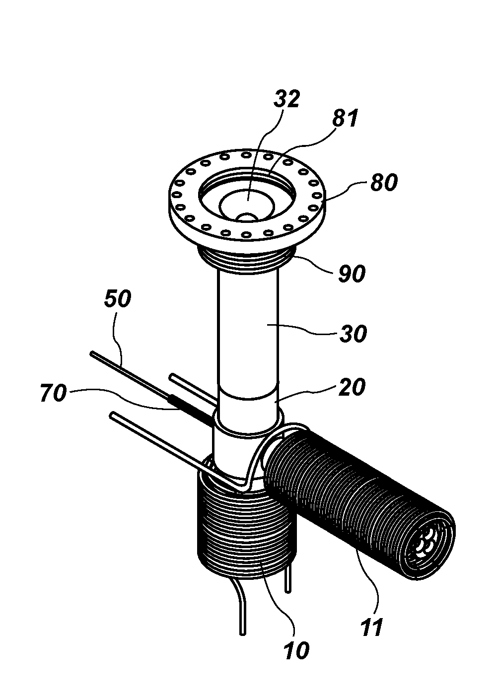
[0090]An effusion cell, comprising: a crucible configured to contain therein a material to be evaporated or sublimated within the effusion cell; a delivery tube configured to deliver evaporated or sublimated material originating from the crucible out from the effusion cell and into a chamber; and at least one radio-frequency (RF) heating element located and configured to heat material contained in the crucible so as to cause evaporation or sublimation of the material in the crucible and flow of the evaporated or sublimated material through the delivery tube and out from the effusion cell.

embodiment 2

[0091]The effusion cell of Embodiment 1, wherein the crucible comprises one or more walls, each wall of the one or more walls having an average wall thickness greater than or equal to 0.036 inch.

embodiment 3

[0092]The effusion cell of Embodiment 2, wherein each wall of the one or more walls has an average wall thickness greater than or equal to 0.25 inch.


PUM

PropertyMeasurementUnit
Timeaaaaaaaaaa
Thicknessaaaaaaaaaa
Thicknessaaaaaaaaaa

Abstract

An effusion cell includes a crucible for containing material to be evaporated or sublimated, a delivery tube configured to deliver evaporated or sublimated material originating from the crucible into a chamber, a supply tube extending from the crucible, the supply tube located and configured to trap condensate originating from the evaporated or sublimated material and to deliver the condensate back to the crucible, and at least one heating element located and configured to heat material in the crucible so as to cause evaporation or sublimation of the material and flow of the evaporated or sublimated material through the delivery tube and out from the effusion cell. The effusion cell is configured such that the crucible can be filled with the material to be evaporated or sublimated without removing the effusion cell from the process vacuum chamber. Semiconductor substrate processing systems may include such effusion cells.

Description

CROSS-REFERENCE TO RELATED APPLICATION[0001]This application claims the benefit of U.S. Provisional Patent Application Ser. No. 62 / 327,323, which was filed Apr. 25, 2016, and also claims the benefit of U.S. Provisional Application Ser. No. 62 / 349,499, which was filed Jun. 13, 2016, the disclosures of which are hereby incorporated herein in their entireties by this reference. The subject matter of this application is also related to the subject matter of U.S. application Ser. No. 15 / 495,488, filed Apr. 24, 2017, and titled “Deposition Systems Including Effusion Sources, and Related Methods” (Attorney Docket No. 3719-P13269.1US), the disclosure of which is also hereby incorporated herein in its entirety by this reference.TECHNICAL FIELD[0002]The present disclosure relates to effusion sources for use with physical vapor deposition systems, to deposition systems including such effusion cells, and to methods of making and using such effusion cells and deposition systems.BACKGROUND[0003]P...

Claims


Application Information

Patent Timeline
IPC IPC(8): C30B23/06C23C14/24C23C14/28C30B23/00
CPCC30B23/066C30B23/005C23C14/243C23C14/28C23C14/246C23C14/26H01J37/3244H01J37/32889H01J37/32082H01J2237/332
Inventor DOOLITTLE, WILLIAM ALAN
Owner INNOVATIVE ADVANCED MATERIALS INC
Features
  • R&D
  • Intellectual Property
  • Life Sciences
  • Materials
  • Tech Scout
  • Unparalleled Data Quality
  • Higher Quality Content
  • 60% Fewer Hallucinations
Learn More