
Mems-based calorimeter, fabrication, and use thereof

a technology of mems-based calorimeters and calorimeters, which is applied in the direction of calorimeters, material thermal analysis, instruments, etc., can solve the problems of dsc instruments that cannot be used widely, require large sample consumption, and cannot be properly handled in a well-defined environment,

Active Publication Date: 2017-10-26
THE TRUSTEES OF COLUMBIA UNIV IN THE CITY OF NEW YORK
View PDF6 Cites 15 Cited by
  • Summary
  • Abstract
  • Description
  • Claims
  • Application Information

AI Technical Summary

Benefits of technology

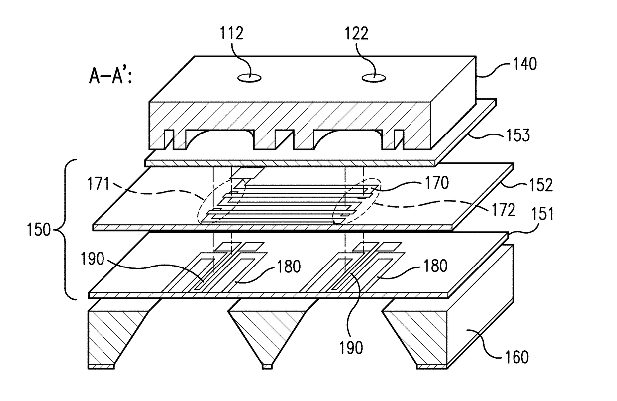
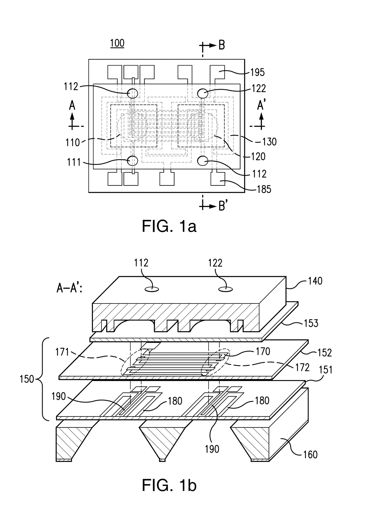
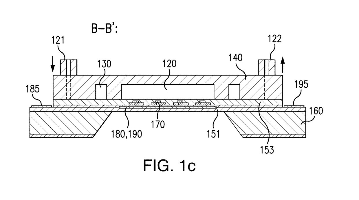
The patent describes a microdevice that includes a reference channel and a sample channel with a thermoelectric sensor. The microdevice can be used to measure the heat involved in a reaction between two substances. The microdevice includes micromixers and the thermoelectric sensor can measure the temperature difference between the reference and sample channels. The microdevice can be made using polymers such as US-8 or parylene. The patent also describes a method for using the microdevice to determine the heat involved in a reaction between two substances. The microdevice can be calibrated using titration and the concentration of the substances can be determined based on the heat measurement. The technical effects of the patent include improved accuracy in measuring heat and the ability to characterize biomolecular interactions.

Problems solved by technology

DSC instruments, however, can be cumbersome and require large sample consumption, which has hindered the widespread application of DSC to biomolecular characterization.
However, it can be difficult to properly handle liquid samples in a well-defined environment in the currently available MEMS calorimeters.
However, these devices can still require a large amount of samples while being limited by significant convective heat leakage due to the continuous flow.
In addition, calibrating existing MEMS DSC devices can be complicated due to a lack of integrated heating elements and temperature sensing.
However, suitable chips can involve thin solid films and operating parameters which are not practicable for biomolecular characterization in solution phase.

Method used


Image

  • Mems-based calorimeter, fabrication, and use thereof
  • Mems-based calorimeter, fabrication, and use thereof
  • Mems-based calorimeter, fabrication, and use thereof

Examples


example 1

on of Microdevice

[0136]This example illustrates a procedure to fabricate the microdevice, which substantially follows the outlined procedure described above in connection with FIG. 2. In particular, a 6-μm thick polyimide film was spin-coated on a silicon wafer (precoated with silicon dioxide). The TMAH etching into the backside of the wafer in the areas that correspond to the calorimetric chambers created an approximately 50 μm-thick residual wafer layer. After the curing of the polyimide, a chromium / gold thin film (5 / 200 μm) was deposited by thermal evaporation onto the polyimide layer. A second layer of polyimide was then coated on the microheaters and temperature sensors. Subsequently, Sb and Bi thin films (0.5 and 1.2 μm) were thermally evaporated and patterned using a standard lift-off process to form a 50-junction thermopile using a standard lift-off process. A layer containing polyimide-PDMS mixture was further coated on the thermopile. The chamber housing structure was fabr...

example 2

ric Measurement

[0137]In this example, the microdevice as fabricated according to Example 1 was calibrated and used to measure thermodynamic properties of certain biomolecules, e.g., thermodynamics of the unfolding of a protein.

A. Principle

[0138]DSC can measure differential heat capacity, i.e., the heat capacity difference between a sample and a reference material, as a function of temperature. When the sample and reference materials are subjected to identical temperature scanning, i.e., their temperatures are varied at a predetermined rate within a range of interest, the thermally induced activity of the sample molecules, which is either exothermic or endothermic, can cause a small temperature difference between the sample and reference materials (i.e., differential temperature or temperature differential). This differential temperature can be detected to reflect the differential power

ΔP=Ps−Pr   (4)

where Ps and Pr are the thermal power generated in the sample and reference materials...

example 3

asurement

[0150]This Example illustrates the method of carrying out a AC-DSC measurement, as described above based on a microdevice presently disclosed. This MEMS AC-DSC approach can potentially enable measurements of low-abundance biomolecules with improved accuracy, as demonstrated by the application of the device to AC-DSC measurements of the unfolding of lysozyme.

A. Principle

[0151]AC-DSC can monitor the differential heat capacity, i.e., the heat capacity difference between a sample and a reference material, by varying the materials' temperatures at a specified constant rate via a thermally isolated enclosure equipped with temperature control functionalities, superimposed with a temporally periodic variation via identical AC modulation heating applied to the sample and reference (FIG. 3). The differential heat capacity can be obtained by the measurement of the differential temperature, i.e., the temperature difference between the sample and reference materials.

B. Fabrication of th...


PUM

PropertyMeasurementUnit
pHaaaaaaaaaa
temperaturesaaaaaaaaaa

Abstract

A MEMS-based calorimeter includes a reference channel, a sample channel, and a thermopile configured to measure a temperature differential between the reference channel and a sample channel. The reference channel and the sample channel each include a passive mixer such as a splitting-and-recombination micromixer. The passive mixer can be formed by a first set of channels in a first layer and a second set of channels in a second layer. Methods for fabricating the MEMS-based calorimeter and methods of using the calorimeter to measure thermodynamic properties of chemical reactions are also provided.

Description

CROSS REFERENCES TO RELATED APPLICATIONS[0001]This application is a continuation-in-part of International Patent Application No. PCT / US2015 / 057384, filed Oct. 26, 2015, which claims priority from U.S. Provisional Application No. 62 / 068,562, filed Oct. 24, 2014, priority to both of which is claimed, and the disclosure of each of which is incorporated by reference herein in their entireties for all purposes.STATEMENT REGARDING FEDERALLY FUNDED RESEARCH[0002]This invention was made with government support under DBI-0650020 awarded by the National Science Foundation. The government has certain rights in this invention.BACKGROUND[0003]Differential scanning calorimetry (DSC) is a thermoanalytical technique that measures heat generated or required in thermally active processes as the temperature of a sample is varied. When applied to biochemical systems, DSC can provide a label-free method to determine the thermodynamic properties of a wide variety of biomolecular interactions and conforma...

Claims


Application Information

Patent Timeline
Patent Type & Authority Applications(United States)
IPC IPC(8): G01N25/48G01K17/00
CPCG01K17/006G01N25/482G01N25/20
Inventor JIA, YUANZHANG, ZHIXINGLIN, QIAO
Owner THE TRUSTEES OF COLUMBIA UNIV IN THE CITY OF NEW YORK
Learn More