Manufacturing method of contact probes for a testing head

Active Publication Date: 2017-10-26
TECHNOPROBE
View PDF4 Cites 6 Cited by
  • Summary
  • Abstract
  • Description
  • Claims
  • Application Information

AI Technical Summary

Benefits of technology

[0042]In particular, the at least one bridge of material can be realized in correspondence of an end portion of the contact probe and the

Problems solved by technology

The involved dimensions make the placing and holding operations of the contact probes to processing frame, and also their following removal, complicated and expensive, especially in terms of manufacturing times and wastes.
Then, the same problems are found when placing the contact probes in the final testing head.
Moreover, those dimensions are extremely limiting for the manufacturing methods of the contact probes.
In particular, in the field of the testing of the latest manufactured integrated circuits, the extremely reduced distance between the contact pads of the devices under test and consequently between the contact probes of the related testing heads hardly challenged the dimensional limits of the traditional manufacturing methods of the contact probes, which in particular use photolithographic, masking,

Method used


Image

  • Manufacturing method of contact probes for a testing head
  • Manufacturing method of contact probes for a testing head
  • Manufacturing method of contact probes for a testing head

Examples


Embodiment Construction

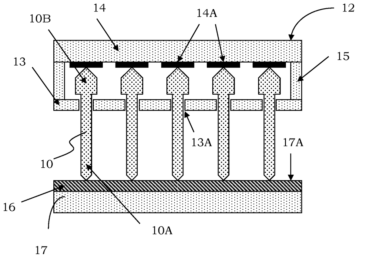
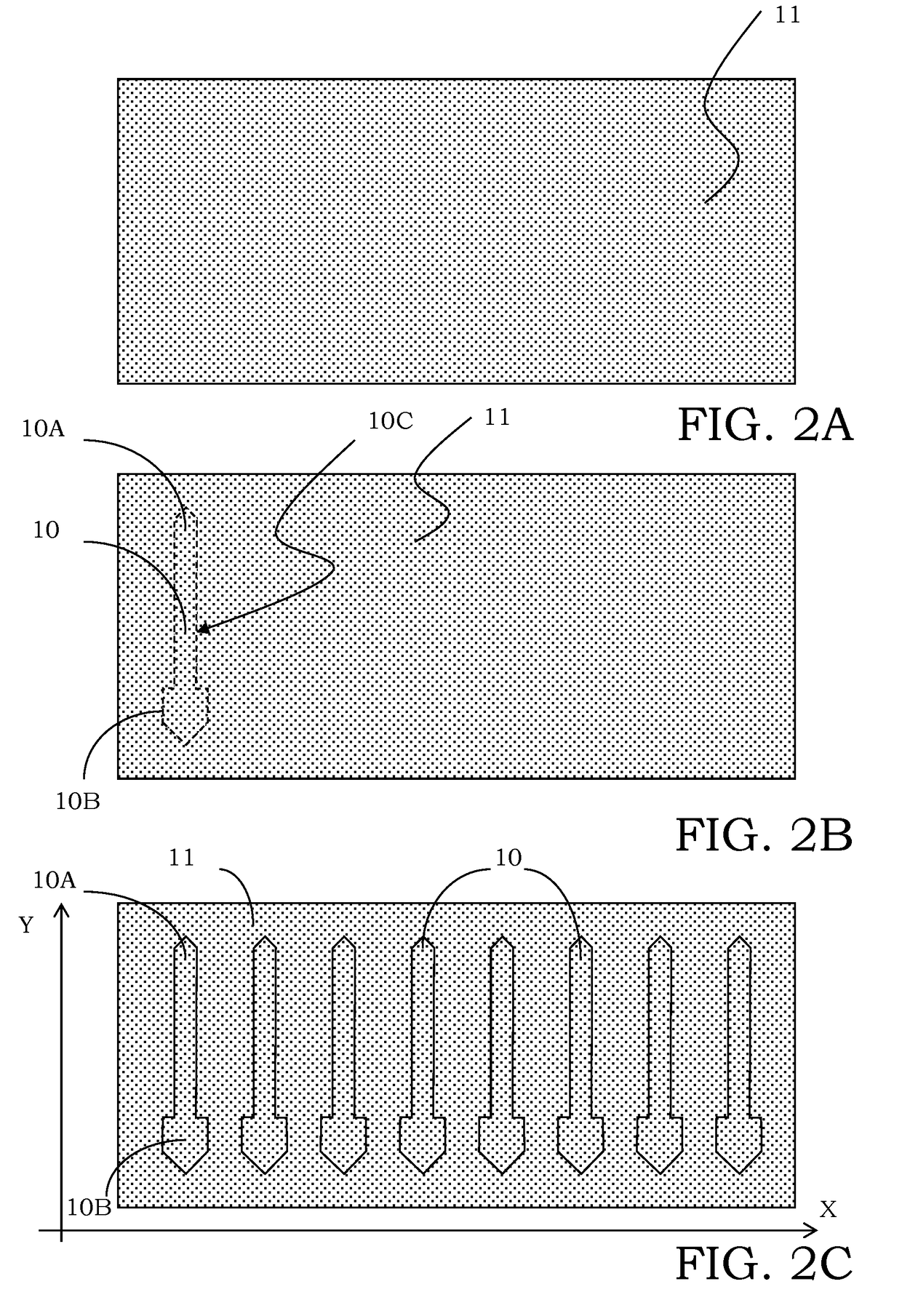
[0073]With reference to those figures, and in particular to FIGS. 2A-2C, a manufacturing method of a plurality of contact probes for a testing head is described, each contact probe being globally indicated with 10.

[0074]It should be noted that the figures represent schematic views and they are not drawn at scale, but instead are drawn so as to emphasize the important characteristics of the disclosure. Moreover, the method steps described in the following do not form a complete process flow for the manufacturing of the contact probes. The present disclosure can be implemented together with manufacturing techniques currently used in the field, and only those commonly used process steps that are necessary for the understanding of the present disclosure are included.

[0075]In particular, the manufacturing method according to the present disclosure includes the steps of:[0076]providing a substrate 11 made of a conductive material, as shown in FIG. 2A; and[0077]defining each contact probe ...


PUM

PropertyMeasurementUnit
Lengthaaaaaaaaaa
Lengthaaaaaaaaaa
Shapeaaaaaaaaaa

Abstract

A manufacturing method of contact probes for a testing head comprises the steps of:—providing a substrate made of a conductive material; and—defining at least one contact probe by laser cutting the substrate. The method further includes at least one post-processing fine definition step of at least one end portion of the contact probe, that follows the step of defining the contact probe by laser cutting, the end portion being a portion including a contact tip or a contact head of the contact probe. The fine definition step does not involve a laser processing and includes geometrically defining the end portion of the contact probe with at least a substantially micrometric precision.

Description

BACKGROUNDTechnical Field[0001]In its more general aspect, the present disclosure refers to a manufacturing method of contact probes for a testing head and the following description is carried out with reference to this application field with the only purpose to simplify its exposition.Description of the Related Art[0002]As it is well known, a testing head (probe head) is essentially a device suitable to place a plurality of contact pads of a microstructure, in particular an electronic device that is integrated on a wafer, into electrical contact with corresponding channels of a testing machine performing the working test thereof, in particular the electrical one, or generically the test.[0003]The test, which is performed on integrated devices, is particularly useful to detect and isolate defective devices yet in the manufacturing step. Therefore, the testing heads usually are used to electrically test the devices that are integrated on a wafer before cutting (singling) and assembly...

Claims


Application Information

Patent Timeline
IPC IPC(8): G01R1/067G01R1/073B44C1/22G01R3/00B23K26/38B23K101/38
CPCG01R1/06744G01R1/07314G01R1/07364B23K2201/38G01R3/00B44C1/22B23K26/38G01R1/07371B23K2101/38G01R1/07307G01R1/07342G01R1/0408G01R1/0433
Inventor VALLAURI, RAFFAELE UBALDO
Owner TECHNOPROBE
Why Eureka
Try Eureka