Optical imaging lens
a technology of optical imaging and optical axis, applied in the field of optical imaging lenses, can solve the problems of reducing the size of the imaging lens while achieving good optical characteristics, overcoming unique challenges, and reducing the distance from the object side surface of the first lens element to the image plane along the optical axis, etc., to achieve good optical characteristics, reduce the field of view, and increase the aperture
- Summary
- Abstract
- Description
- Claims
- Application Information
AI Technical Summary
Benefits of technology
Problems solved by technology
Method used
Image
Examples
first embodiment
[0109]FIG. 7 part a shows the longitudinal spherical aberration, wherein the horizontal axis of FIG. 7 part a defines the focus, and the vertical axis of FIG. 7 part a defines the field of view. FIG. 7 part b shows the astigmatism aberration in the sagittal direction, wherein the horizontal axis of FIG. 7 part b defines the focus, and the vertical axis of FIG. 7 part b defines the image height. FIG. 7 part c shows the astigmatism aberration in the tangential direction, wherein the horizontal axis of FIG. 7 part c defines the focus, and the vertical axis of FIG. 7 part c defines the image height. FIG. 7 part d shows the variation of the distortion aberration, wherein the horizontal axis of FIG. 7 part d defines the percentage, and the vertical axis of FIG. 7(d) defines the image height. The three curves with different wavelengths (470 nm, 555 nm, 650 nm) represent that off-axis light with respect to these wavelengths may be focused around an image point. From the vertical deviation o...
tenth embodiment
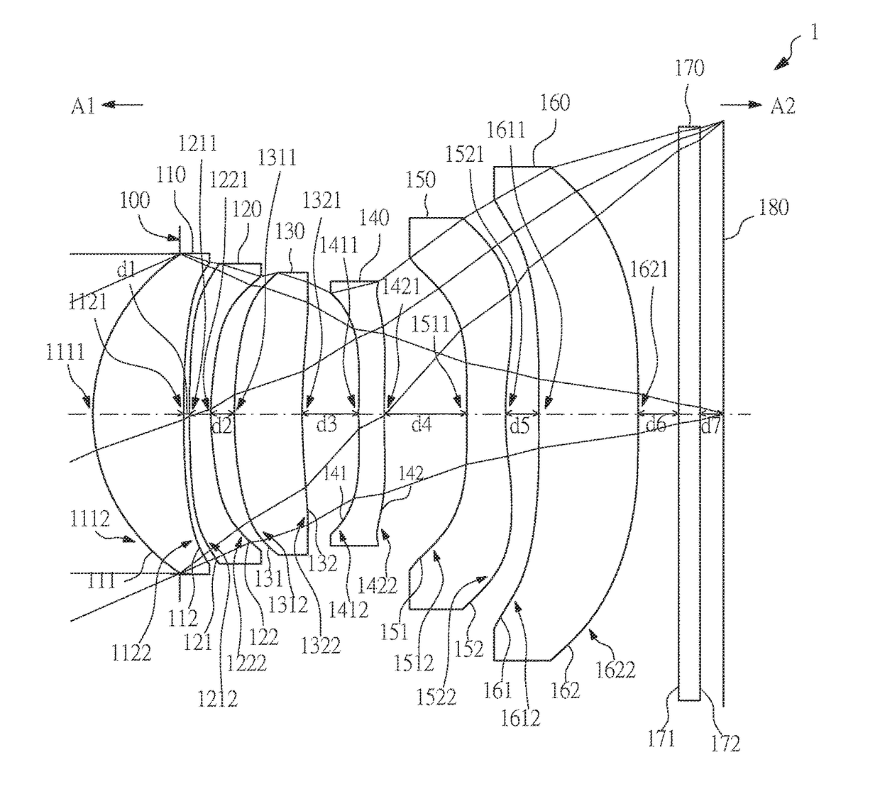
[0187]Here, for clearly showing the drawings of the present embodiment, only the surface shapes which are different from that in the tenth embodiment are labeled. Please refer to FIG. 48 for the optical characteristics of each lens elements in the optical imaging lens 11 of the present embodiment.
[0188]From the vertical deviation of each curve shown in FIG. 47 part a, the offset of the off-axis light relative to the image point may be within about ±0.06 mm. Referring to FIG. 47 part b, the focus variation with respect to the three different wavelengths (470 nm, 555 nm, 650 nm) in the whole field may fall within about ±0.05 mm. Referring to FIG. 47 part c, the focus variation with respect to the three different wavelengths (470 nm, 555 nm, 650 nm) in the whole field may fall within about ±0.06 mm. Refer to FIG. 47 part d, the variation of the distortion aberration of the optical imaging lens 11 may be within about ±1.6%.
[0189]Please refer to FIG. 54A and FIG. 54B for the values of EF...
PUM
 Abstract
Description
Claims
Application Information
 - R&D
- Intellectual Property
- Life Sciences
- Materials
- Tech Scout
- Unparalleled Data Quality
- Higher Quality Content
- 60% Fewer Hallucinations
Browse by: Latest US Patents, China's latest patents, Technical Efficacy Thesaurus, Application Domain, Technology Topic, Popular Technical Reports.
© 2025 PatSnap. All rights reserved.Legal|Privacy policy|Modern Slavery Act Transparency Statement|Sitemap|About US| Contact US: help@patsnap.com


