
Real-time autonomous weather and space weather monitoring

a real-time autonomous and weather technology, applied in the field of autonomous weather monitoring, can solve the problems of affecting the ability to accurately scintillation forecasting, affecting the accuracy of regional and global ionospheric specification, and affecting the ability to accurately forecast regional and global ionospheric conditions, etc., and achieves high accuracy.

Active Publication Date: 2017-11-09
ATMOSPHERIC & SPACE TECH RES ASSOCS
View PDF5 Cites 17 Cited by
  • Summary
  • Abstract
  • Description
  • Claims
  • Application Information

AI Technical Summary

Benefits of technology

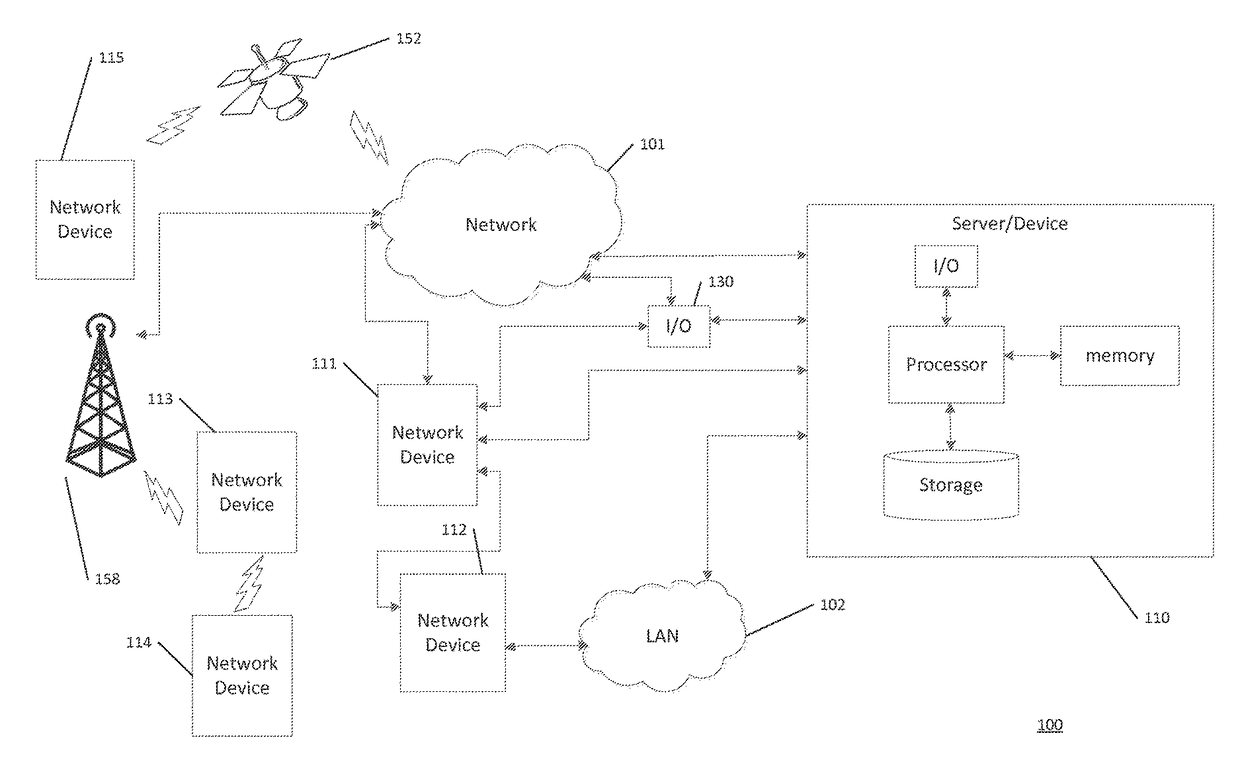
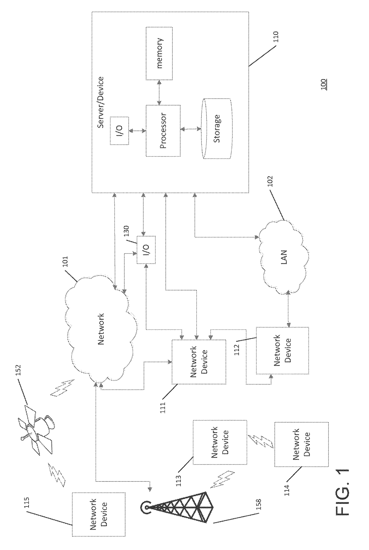
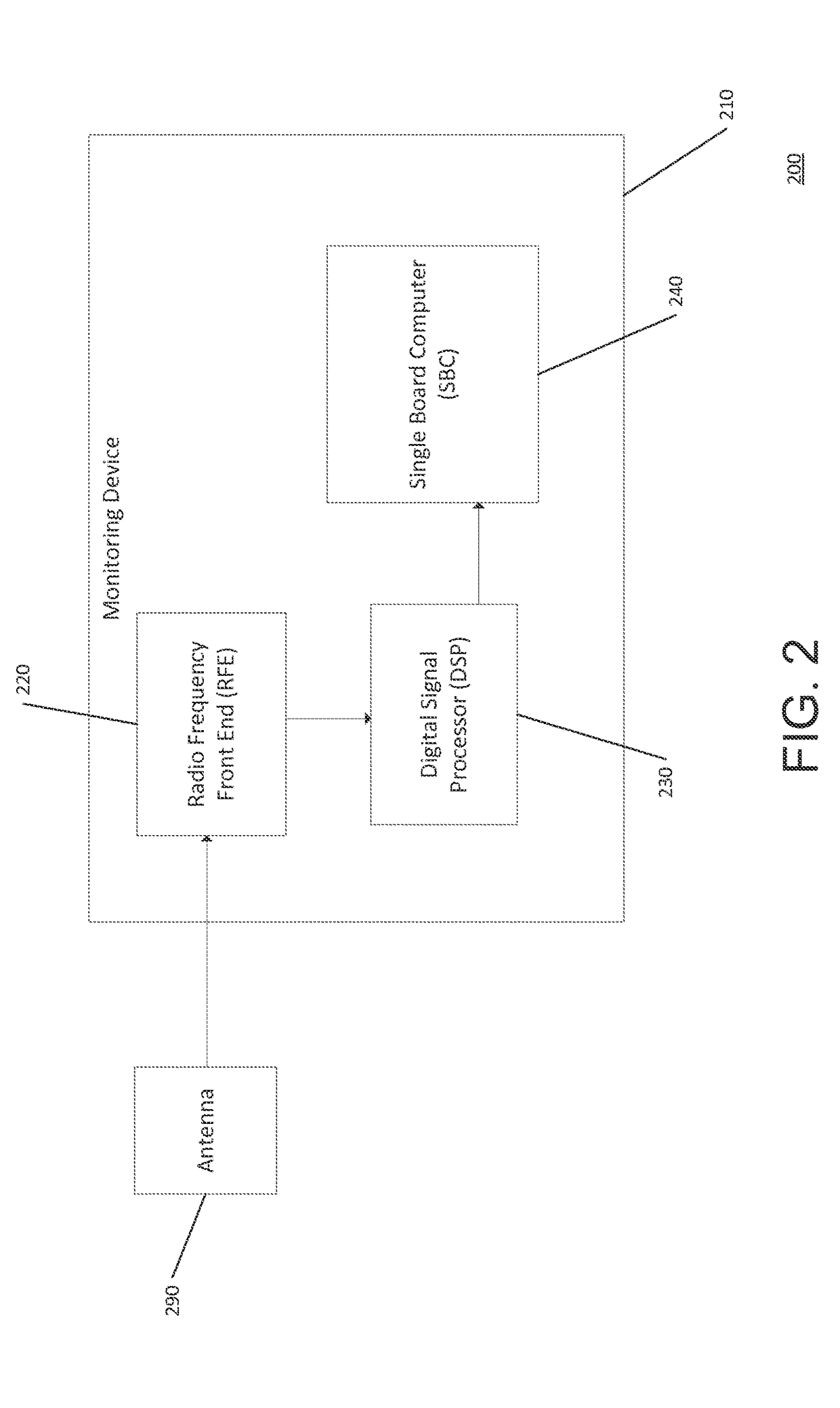
The present invention provides a system for monitoring the ionosphere in real-time over a low data-rate satellite link. The system is lightweight, low-power, and fully-autonomous. It can provide accurate data on ionospheric TEC and scintillation parameters, as well as error estimates and health and status information. The system can operate remotely and over areas where low power and satellite communications are essential. It uses a high-rate phase navigation solution to calculate the perturbation of the radio signals received by the monitoring device, which is then filtered to remove drift motion. The system can also calculate the tilt angle of the antenna and the amplitude of the perturbation based on the pitch, yaw, and roll motions of the monitoring device and the position of the orbital navigation satellite.

Problems solved by technology

However, one deficiency with the related art is that the availability of such ground-based ionospheric monitoring systems is extremely limited in certain environments (e.g., oceanic regions, theaters / tactical environments and / or other locations).
The lack of data from oceanic regions and theater locations adversely impacts the ability for accurate regional and global ionospheric specification and scintillation forecasting.
Traditional ground-based ionospheric monitoring systems have not permitted coverage of large ocean areas or on-demand theater coverage.

Method used


Image

  • Real-time autonomous weather and space weather monitoring
  • Real-time autonomous weather and space weather monitoring
  • Real-time autonomous weather and space weather monitoring

Examples


example

[0173]Without intending to limit the scope of the invention, the following example illustrates how various embodiments of the invention may be made and / or used.

[0174]This Example illustrates the deployment of a monitoring device in an oceanic environment and the calculating of the ionospheric scintillation and the wave height.

[0175]In this Example, the experimental setup included a monitoring device mounted on a liquid robotics wave glider SV2 platform. The monitoring device was configured to record raw GPS L1 spectrums. The monitoring device included an antenna, radio frequency front end (RFE) hardware, USB digital acquisition board, embedded Linux computer, and storage device.

[0176]The antenna was an Antcom 53G1215A-XT-1 dual frequency active GPS patch antenna for receiving a radio signal from a number of GPS satellites.

[0177]The radio frequency front end (RFE) hardware was configured to down convert the GPS L1 spectrum to an intermediate frequency of 1.610476 MHz. The GPS RF fron...

example method

[0183]Step 1: A 32 hour ocean test was conducted in Hawaii from 17:50 UTC on the first day to 1:30 UTC on the third day and data was obtained. The data included the raw GPS L1 spectrum during that time range, including data from all 32 GPS satellites, e.g., PRN1-PRN32.

[0184]Step 2: This raw spectrum was post-processed in order to acquire and track the signals from any and all GPS satellites contained within. This process includes the calculation of all typical GNSS observables, including 100 Hz integrated carrier phase, in-phase accumulation, quadrature accumulation, GPS time, and receiver time, as well as 1 Hz pseudorange, integrated carrier phase, GPS time, receiver time, Doppler frequency, SV elevation, SV azimuth, C / NO, data validity flag, cycle slip flag, signal acquisition status, PRN, SV health, and 0.01 Hz S4, σΦ, τ0, scintillation power ratio, GPS time, reference channel status, and PRN for each satellite being tracked, as well as 1 Hz receiver X / Y / Z position, receiver X / Y / ...


PUM


Abstract

A method of calculating ionospheric scintillation includes calculating a motion-corrected perturbation of a GNSS radio signal received by a monitoring device deployed in an oceanic environment. The method includes calculating the σφ using the high rate phase of the GNSS signal adjusted by removing the change in distance between the monitoring device and the GNSS satellite. The calculating the σo may further include passing the adjusted high rate phase through a high pass filter to remove a drift motion of the monitoring device. The method further includes calculating the S4 through calculating a tilt angle between the antenna of the monitoring device with the GNSS satellite and adjusting the antenna gain through known gain pattern of the antenna. The wave height of the oceanic environment may be calculated by detrending the antenna height to remove low frequency motion when a high rate position of the monitoring device is calculated.

Description

CROSS REFERENCE TO RELATED APPLICATION[0001]The present application claims the benefits of and priority, under 35 U.S.C. §119(e), to U.S. Provisional Application Ser. No. 61 / 861,948, filed Aug. 2, 2013, entitled “Motion Correction on Moving Platform” and U.S. Provisional Application Ser. No. 61 / 901,426, filed Nov. 7, 2013, entitled “Real-Time Autonomous Weather and Space Weather Monitoring;” each of the above-identified applications being fully incorporated herein by reference.BACKGROUNDField of the Invention[0002]This invention relates generally to autonomous weather monitoring and specifically to apparatus, systems, and / or methods for ionospheric monitoring, modeling, and estimation of the same.Discussion of the Background[0003]Ionospheric variability can have a significant impact on operational capabilities in many areas, including communications, navigation, and surveillance operations. As such, ionospheric monitoring is important for the support of requirements for global space...

Claims


Application Information

Patent Timeline
Patent Type & Authority Applications(United States)
IPC IPC(8): G01S13/95G01S19/14G01S13/74G01S19/07G01W1/02G01S19/40
CPCG01S13/955G01S19/14G01S13/74G01W1/02G01S19/40G01S19/07G01S19/43G01S19/47G01S19/072Y02A90/10
Inventor REYNOLDS, ADAM SCOTTAZEEM, SYED MOHAMMED IRFANCROWLEY, GEOFFREY
Owner ATMOSPHERIC & SPACE TECH RES ASSOCS
Learn More