Dust separation apparatus and intelligent control system including the apparatus

a technology of intelligent control system and dust separation apparatus, which is applied in the direction of vortex flow apparatus, separation process, cleaning equipment, etc., can solve the problems of secondary pollution of dust, high prone to clogging of filter screen, and severe impact on dust removal effect, so as to reduce the occurrence of clogging and reduce the concentration of dust, the overall effect of dust removal is good, and the clogging is less prone to clogging

Active Publication Date: 2017-11-23
NANJING HAIFENG ENVIRONMENTAL PROTECTION TECH CO LTD
View PDF1 Cites 17 Cited by
  • Summary
  • Abstract
  • Description
  • Claims
  • Application Information

AI Technical Summary

Benefits of technology

[0012]To overcome the foregoing technical defects one by one, the present invention is intended to provide several technical solutions that are technically correlated to each other. To solve the defects 1 to 3, a first objective of the present invention is to provide a dust separation apparatus. By means of the dust separation apparatus, the dust removal efficiency is high, the emission concentration is low, the dust removal effect is good, a filter screen is less prone to clogging, dust is easy to clean, the secondary pollution of dust is avoided, the device has a small volume, and the working noise is low.

Problems solved by technology

1. By using the inertial separation method, only dust having relatively large particle diameters can be separated. About 50% of dust is separated. The rest dust needs to be filtered through the filter cylinder. The filter cylinder is required to filter a large amount of dust, and a substantial part of dust is attached to a wall of the filter cylinder. Thus, the filter screen is highly prone to clogging, and the dust removal effect is severely affected.
2. The large amount of dust enters the filter cylinder. The dust collection bag below the filter cylinder requires to be frequently replaced. When the dust collection bag is removed, some dust is scattered, resulting in secondary pollution of dust.
3. To improve the separation efficiency of dust, the conical body is designed to be relatively long, the device is relatively high and has a large volume, and the device has much vibration and noise and is also not convenient to move.
4. The dust collection box generally has a floor type. When the ground has an uneven surface, the connection between the dust collection box and the dust separation device is poorly sealed, resulting in phenomena that air leaks and dust escapes.
5. The device can support only simple ON and OFF operations, without intelligent control capability. The device cannot be started or stopped in coordination with a machine that generates dust. Operation data of the device cannot be collected in real time. The working condition of the device in operation cannot be monitored in real time based on the collected data, and further, intelligent control cannot be performed based on the data of the working condition.
6. The device can be operated at only a fixed rotational speed, without capabilities of adjusting the speed and controlling the power constant at a rated power. When a pipe network environment changes, a change in the power of the motor cannot be monitored on line in real time, and a rotational speed of the motor cannot be automatically adjusted to make the motor be constant at the rated power. The efficiency of the blower is also lower than the maximum designed efficiency. When a small-diameter dust collection pipe is used for dust collection, the power of the motor and the efficiency of the blower are reduced and the dust collection capability is reduced. When a large-diameter dust collection pipe is used for dust collection, the device may be overloaded.

Method used


Image

  • Dust separation apparatus and intelligent control system including the apparatus
  • Dust separation apparatus and intelligent control system including the apparatus
  • Dust separation apparatus and intelligent control system including the apparatus

Examples


embodiment 1

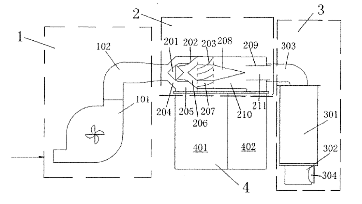
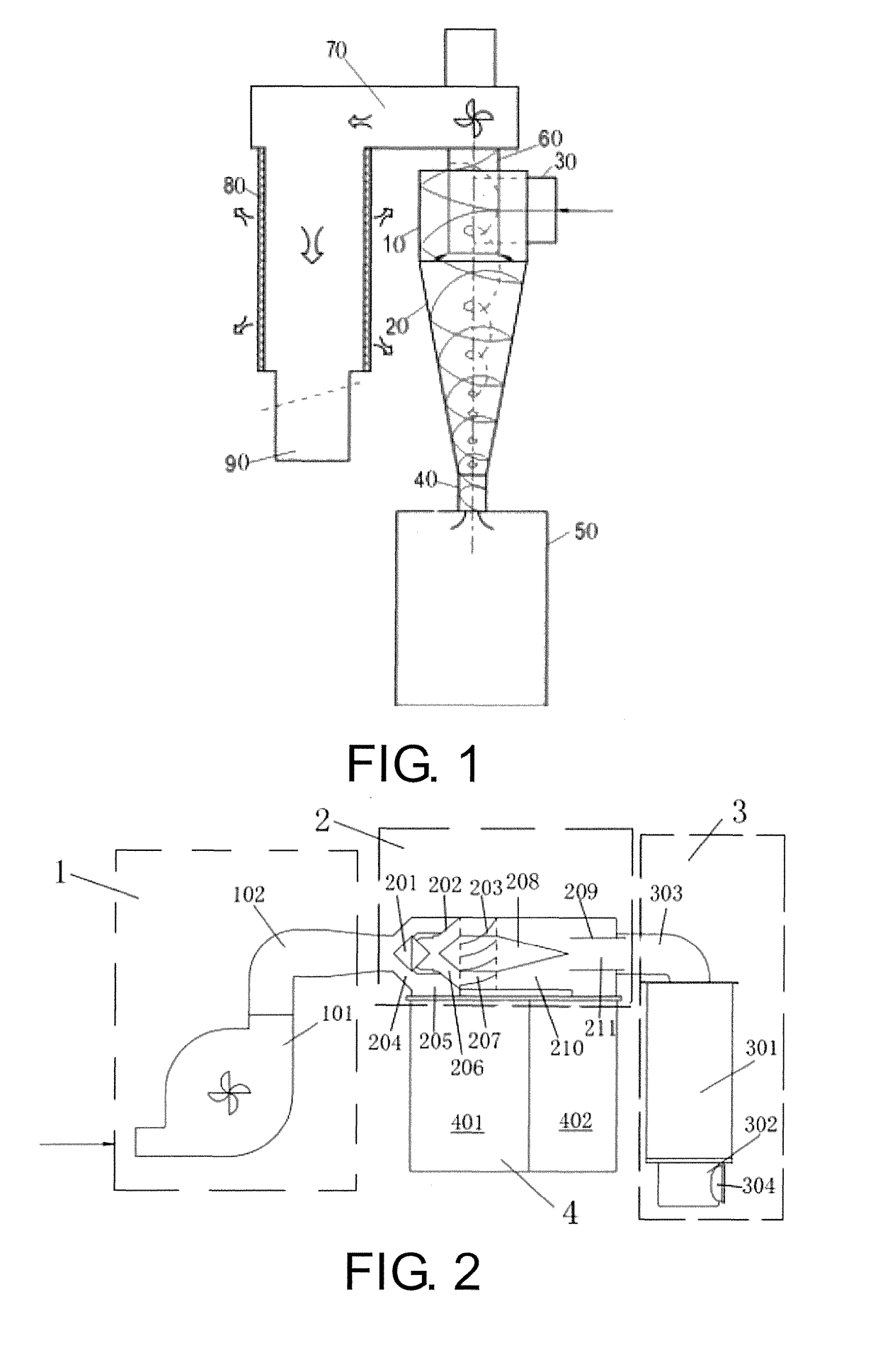
[0053]Referring to FIG. 2, a dust separation apparatus includes a dust intake unit 1 including a blower, an inertial separation unit, a centrifugal separation unit, and a filtering separation unit 3. The dust intake unit 1, the inertial separation unit, the centrifugal separation unit, and the filtering separation unit 3 are sequentially connected in series and together form a horizontal structure. The inertial separation unit and the centrifugal separation unit are connected in a horizontal-axis direction to form an inertial and centrifugal separation unit 2. A dust collection box 4 is provided below and connected to the inertial and centrifugal separation unit 2.

[0054]The expression “together form a horizontal structure” may be understood to mean that generally a length of the structure is greater than a height of the structure, where the main separation work is completed in a state of a horizontal-axis direction. The expression “sequentially connected in series” may be understood...

embodiment 2

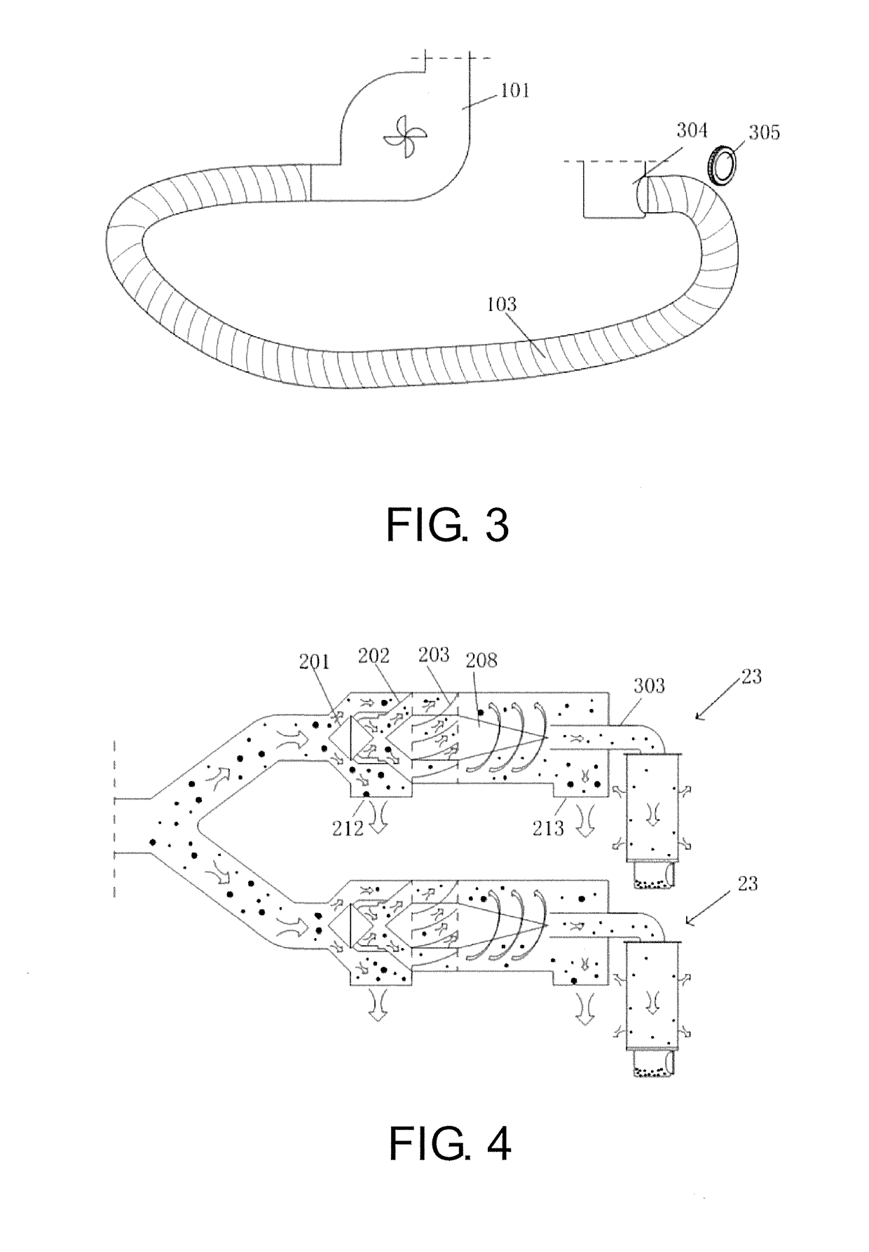
[0071]This embodiment is different from Embodiment 1 that, referring to FIG. 6, the inertial separation unit, the centrifugal separation unit, and the filtering separation unit that are sequentially connected in series form a plurality of separation units 23. The word “a plurality of” refers to “two or more”. FIG. 6 shows two separation units 23. Each of the separation units is connected to the dust intake unit. Where the dust intake unit has a fixed intake air volume for dust, a pipe diameter of each separation unit is designed such that an air flow rate is controlled between 13 m / s and 22 m / s. In this way, the centrifugal force of dust particles is increased, thereby improving the separation efficiency of dust.

[0072]For the plurality of separation units 23 that are connected in parallel, the primary separation ports 212 are all connected to the first receiving chamber in the dust collection box, and the secondary separation ports 213 are all connected to the second receiving chamb...

embodiment 3

[0073]An intelligent control system for dust separation includes the dust separation apparatus according to any of the solutions above and an intelligent control unit. The intelligent control unit includes a master-machine controller mounted on the dust separation apparatus and a slave-machine controller mounted on a dust-generating device for dust removal. The master-machine controller includes a first MCU control module, an I / O interface module, and a first WiFi wireless communication module, and the MCU control module is connected to an external device through the I / O interface module, and communicates with the slave-machine controller through the WiFi wireless communication module. The slave-machine controller consists of a second MCU control module, an interface module, a second WiFi wireless communication module, and a current transformer. The current transformer is configured to detect a current value of a motor of the dust-generating device, and the second MCU control module...


PUM

PropertyMeasurementUnit
flow speedaaaaaaaaaa
diameteraaaaaaaaaa

Abstract

The dust separation apparatus includes a dust intake unit including a blower, an inertial separation unit, a centrifugal separation unit, and a filtering separation unit. The dust intake unit, the inertial separation unit, the centrifugal separation unit, and the filtering separation unit are sequentially connected in series and together form a horizontal structure. The inertial separation unit and the centrifugal separation unit are connected in a horizontal-axis direction to form an inertial and centrifugal separation unit. A dust collection box is provided below and connected to the inertial and centrifugal separation unit. The filtering separation unit includes a dust collection barrel. The intelligent control system includes the dust separation apparatus and an intelligent control unit.

Description

BACKGROUND OF THE INVENTIONField of the Invention[0001]The present invention belongs to the technical field of dust separation, collection, and filtering, and more particularly to a dust separation apparatus and an intelligent control system including the apparatus.Description of Related Art[0002]At present, an inertial separation technology, a filtering separation technology or a combination of the two technologies is used in almost all dust separation apparatuses. The most commonly used at present is a cyclone dust separation apparatus. Such an apparatus is an apparatus that combines an inertial separation technology and a filtering separation technology.[0003]Referring to FIG. 1, the cyclone dust separation apparatus includes a cylindrical body 10, a conical body 20, an air inlet pipe 30, a dust discharge pipe 40, a dust collection box 50, an air discharge pipe 60, a transfer chamber 70, a filter cylinder 80, and a dust collection bag 90. The air inlet pipe 30 is connected to the...

Claims


Application Information

Patent Timeline
Patent Type & Authority Applications(United States)
IPC IPC(8): B04C5/103B04C5/185B04C11/00B01D45/14B04C9/00B01D50/00
CPCB04C5/103B04C5/185B04C9/00B04C2009/005B01D50/002B04C11/00B04C2009/002B01D45/14B01D45/12B01D45/04B04C3/06B04C2003/006B04C7/00A47L9/1625A47L9/1683B04C5/26B01D50/20
Inventor HUA, YIXU, QINGHAILI, XINNINGQIN, XIAOGANGPAN, HUIZISUN, HUAZHONG
Owner NANJING HAIFENG ENVIRONMENTAL PROTECTION TECH CO LTD
Why Eureka
Try Eureka