
Combustion Gas Sensor Assembly for Engine Control

a gas sensor and combustion gas technology, applied in the direction of electric control, machines/engines, instruments, etc., can solve the problems of affecting the operation of the engine, so as to achieve the effect of resisting damage and fouling, high spatial coherence, and advantageously resisting fouling

Active Publication Date: 2017-12-21
WISCONSIN ALUMNI RES FOUND
View PDF13 Cites 0 Cited by
  • Summary
  • Abstract
  • Description
  • Claims
  • Application Information

AI Technical Summary

Benefits of technology

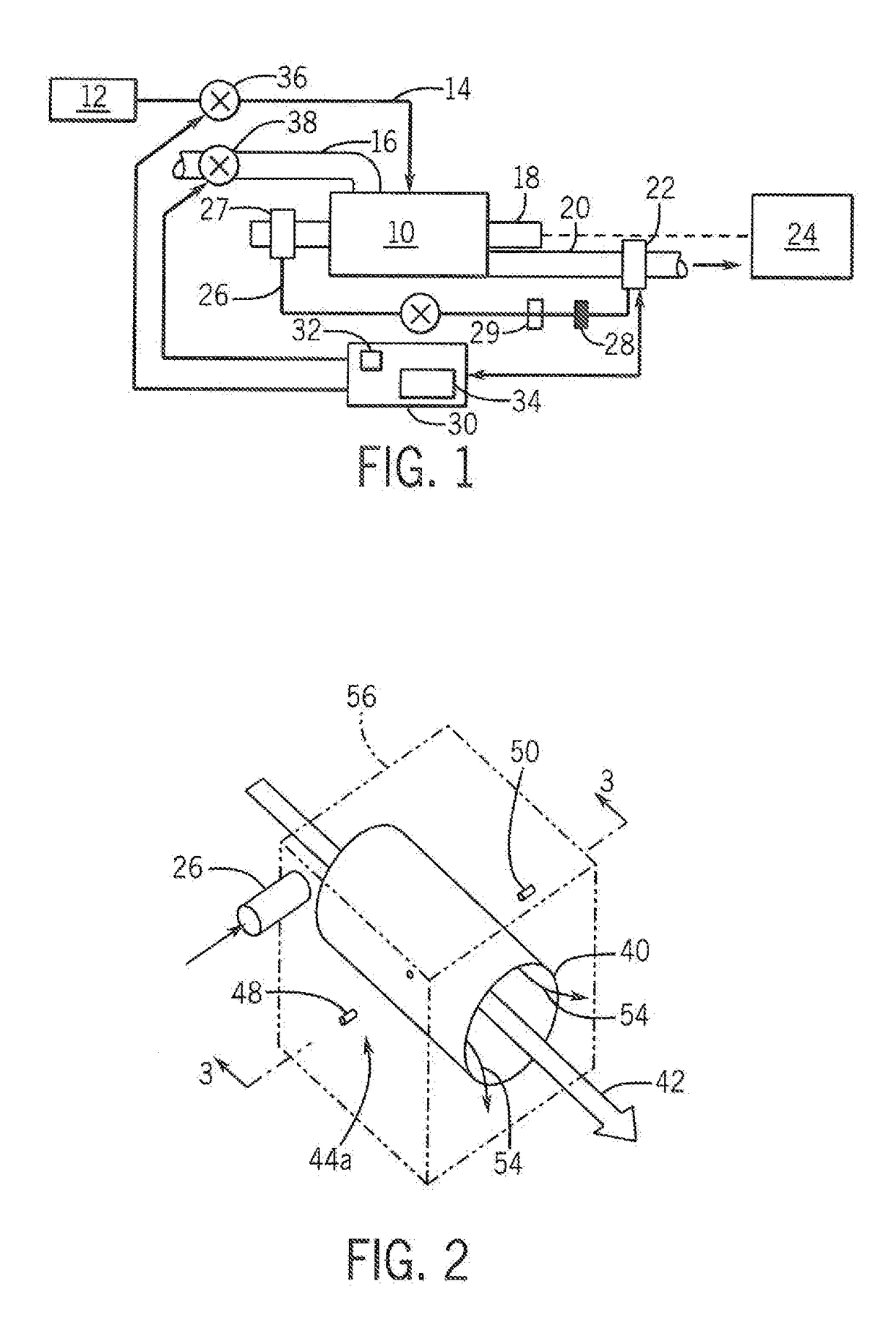
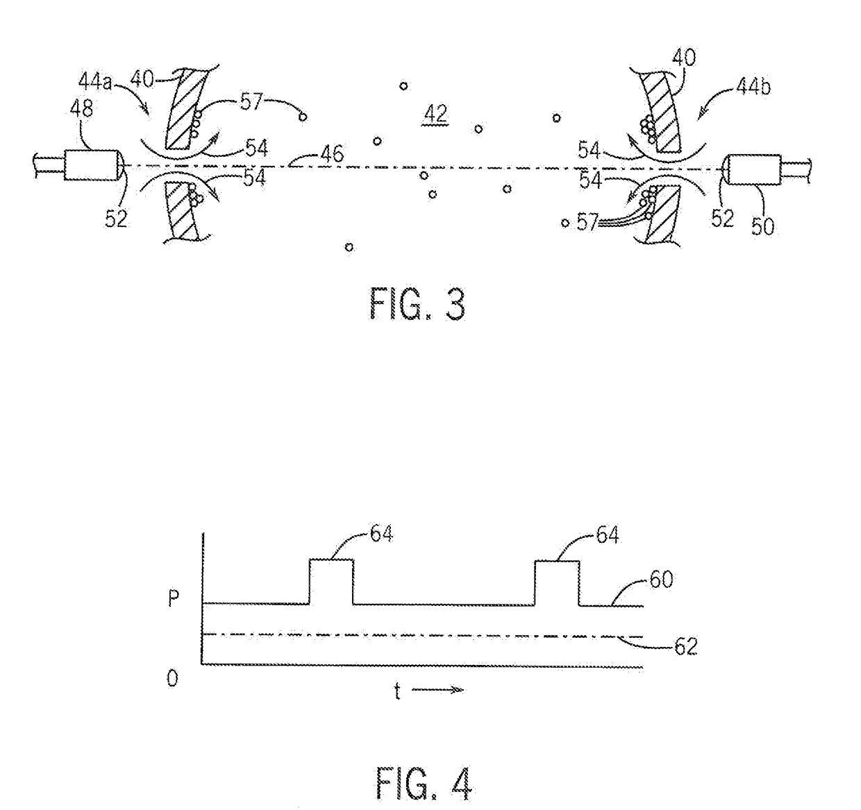
The present invention provides an optical assembly for long-term monitoring of combustion engines with reduced power usage and degradation of the sensor. This is possible through the use of a small opening into the combustion conduit, which allows air flow to prevent damage and fouling of the optical sensors. The assembly includes a high spatial coherence light emitter and a light receiver to detect the light after passage through the combustion gases and the small opening to produce an electrical signal indicating spectral absorption of the light by the combustion gases in at least two frequencies. The invention provides a reliable and accurate means to monitor combustion engines.

Problems solved by technology

In addition, the extremely small hole size can block insect entry, moisture, and dust accumulation.

Method used


Image

  • Combustion Gas Sensor Assembly for Engine Control
  • Combustion Gas Sensor Assembly for Engine Control
  • Combustion Gas Sensor Assembly for Engine Control

Examples


Embodiment Construction

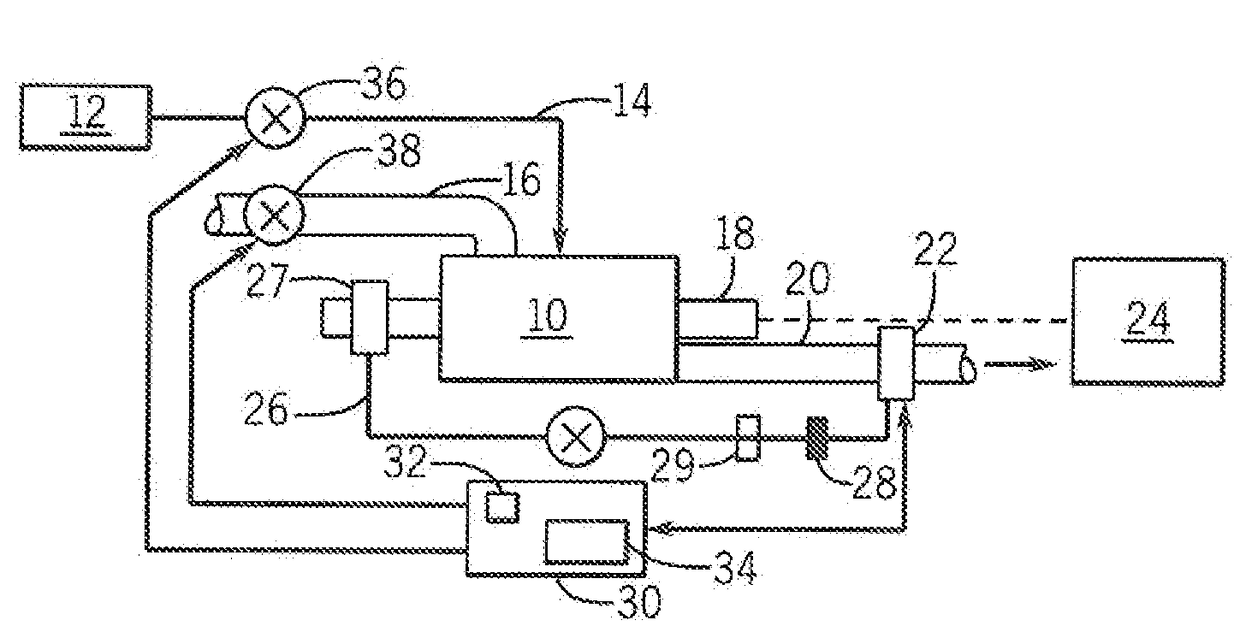
[0041]Referring now to FIG. 1, a combustion engine 10, including but not limited to a gas turbine, diesel or gasoline engine, may receive fuel 12 over fuel line 14 and air through an air intake 16 to provide mechanical energy through a driveshaft 18 using energy released from the combustion of the air and fuel. The driveshaft 18 will typically drive a load 24, for example, an electrical generator, pump, vehicle or the like.

[0042]Combustion products from the combustion engine 10 are conducted through an exhaust pipe 20 that passes through a sensor system 22 of the present invention. These combustion products are then received by pollution control measures (not shown) and discharged into the atmosphere. Alternatively, the pollution control measures could be located before the sensor system, for example, when the sensor system is monitoring such control measures.

[0043]A small portion of the power from the combustion engine 10 may be used to provide a source of pressurized air over air ...


PUM

PropertyMeasurementUnit
areaaaaaaaaaaa
areaaaaaaaaaaa
diameteraaaaaaaaaa

Abstract

An optical sensor for sensing combustion products avoids fouling and damage to optical components by using a “windowless” design in which an air curtain through an orifice provides a constantly refreshing transparent shield protecting the optical components from corrosive combustion gases and resisting the accumulation of particulates that might otherwise foul a static window.

Description

STATEMENT REGARDING FEDERALLY SPONSORED RESEARCH OR DEVELOPMENT[0001]--CROSS REFERENCE TO RELATED APPLICATION[0002]--BACKGROUND OF THE INVENTION[0003]The present invention relates to combustion gas sensors and in particular to an optical sensor adapted for continuous engine exhaust monitoring.[0004]Accurate, real-time information about the combustion gases and particulates produced by engines is increasingly important in the efficient control of combustion engines such as automotive gasoline engines but also including other mobile and stationary engines such as gas turbine engines. This information can be obtained by spectrographic analysis of combustion products using optical sensors that measure the absorption of light in different frequency bands as the light passes through combustion gases.[0005]While such spectrographic sensors are routinely used in experimental environments, practical use for engine control requires a highly reliable sensor that can operate with minimal mainte...

Claims


Application Information

Patent Timeline
Patent Type & Authority Applications(United States)
IPC IPC(8): G01M15/10G01N21/15F02D41/14G01N21/3504
CPCG01M15/108F02D41/1451G01N2201/06113G01N21/15G01N2021/151G01N21/3504
Inventor SANDERS, SCOTT THOMAS
Owner WISCONSIN ALUMNI RES FOUND
Learn More