Capacitor circuit, circuit device, physical quantity detecting device, electronic apparatus, and moving object

Active Publication Date: 2017-12-21
SEIKO EPSON CORP
View PDF1 Cites 6 Cited by
  • Summary
  • Abstract
  • Description
  • Claims
  • Application Information

AI Technical Summary

Benefits of technology

[0004]An advantage of some aspects of the invention is to provide a capacitor circuit, a circuit device, a physical quantity detectin

Problems solved by technology

For example, a successive approximation type A/D conversion circuit or the like using the capacitor circuit has a problem in that a layout configuration or signal wiring is complicated and thus results

Method used


Image

  • Capacitor circuit, circuit device, physical quantity detecting device, electronic apparatus, and moving object
  • Capacitor circuit, circuit device, physical quantity detecting device, electronic apparatus, and moving object
  • Capacitor circuit, circuit device, physical quantity detecting device, electronic apparatus, and moving object

Examples


Embodiment Construction

[0053]Hereinafter, preferred embodiments of the invention will be described in detail. The embodiments described below do not unduly limit the details of the invention set forth in the appended claims. Not all of the configurations described in the embodiments may necessarily be indispensable as solving means of the invention.

1. Capacitor Circuit

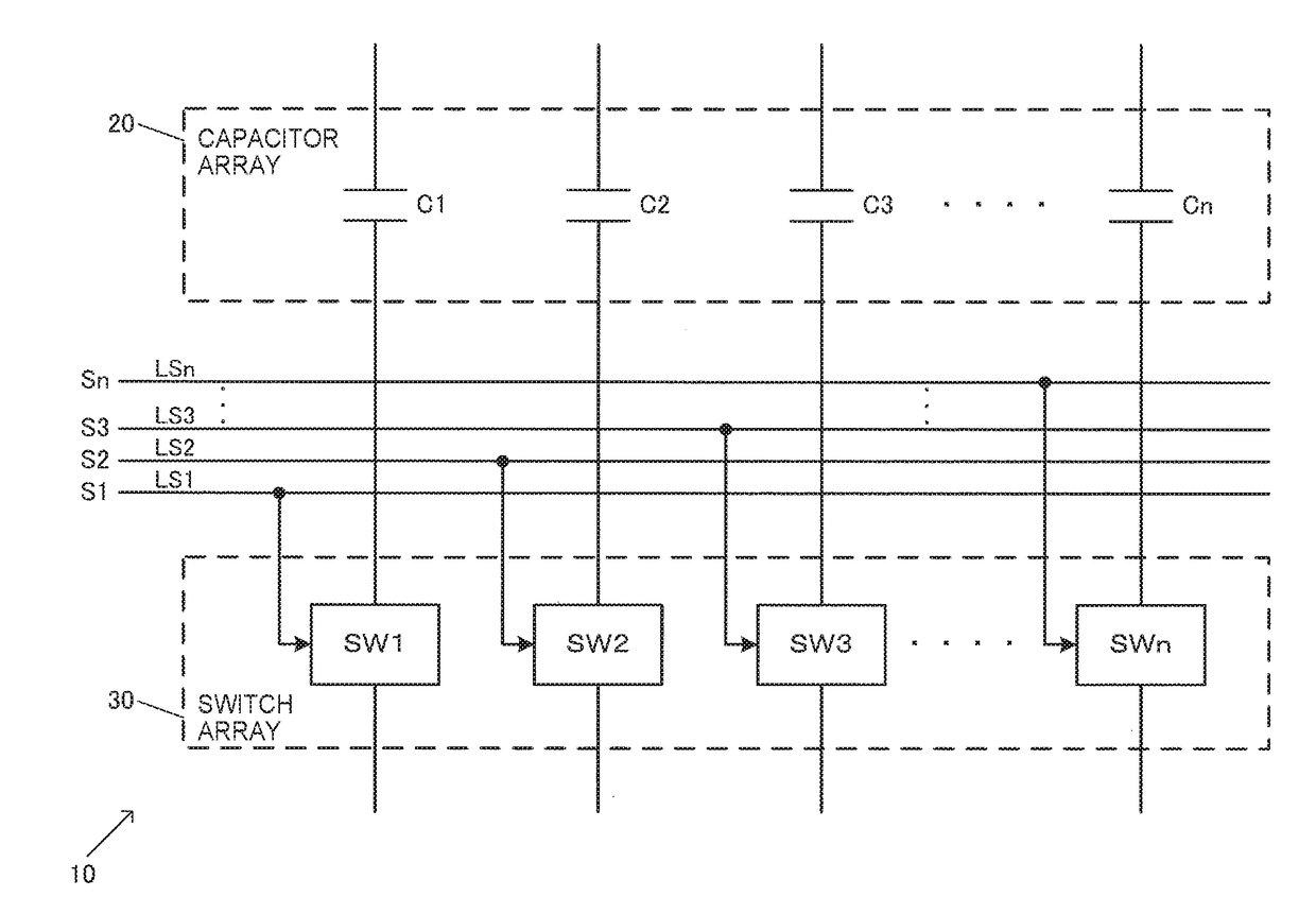
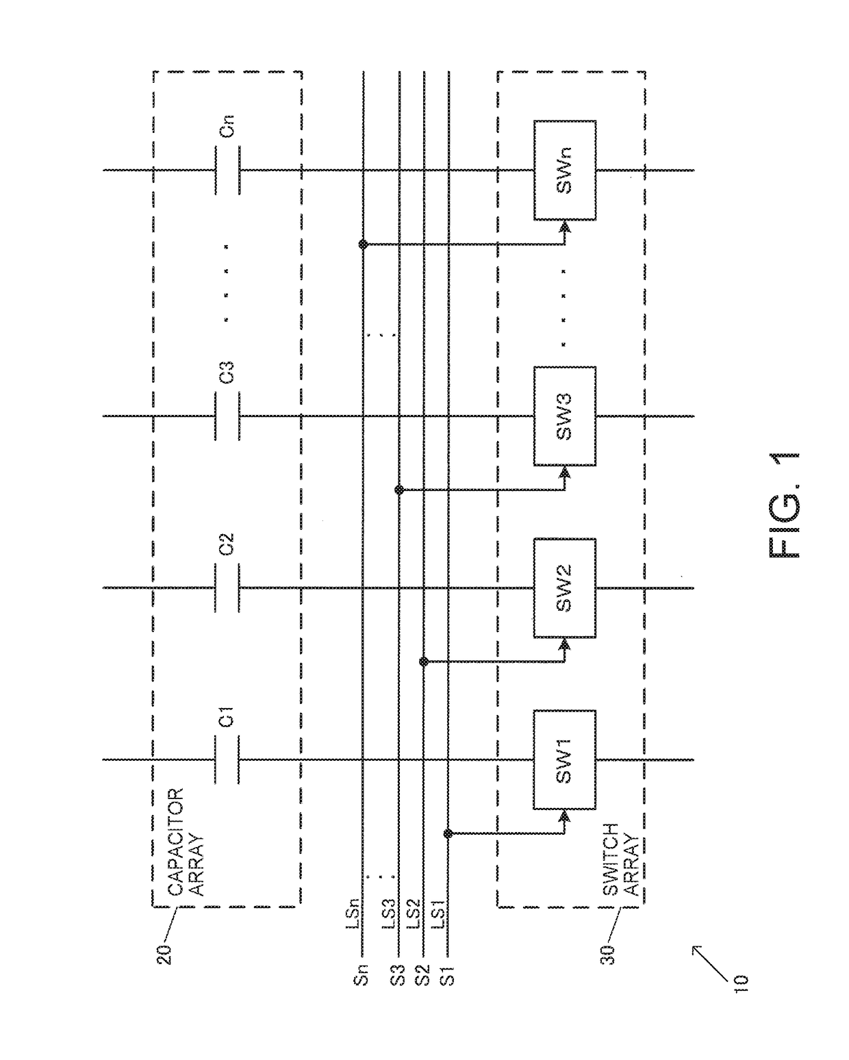
[0054]FIG. 1 shows a configuration example of a capacitor circuit 10 of an embodiment. The capacitor circuit 10 includes a capacitor array 20 including a plurality of capacitors C1 to Cn (n is an integer of 2 or more), and a switch array 30 including a plurality of switch circuits SW1 to SWn (switch elements). For example, in the switch circuits SW1 to SWn, the switch circuits are connected to the capacitors C1 to Cn of the capacitor array 20. For example, the switch circuit SW1 is connected to one end of the capacitor C1, and the switch circuit SW2 is connected to one end of the capacitor C2. The same applies to the connection configuration...


PUM


Abstract

A capacitor circuit includes: a capacitor array including a plurality of capacitors; a switch array including a plurality of switch circuits, the switch circuits being respectively connected to the capacitors of the capacitor array; a plurality of switch control signal lines supplied with a plurality of switch control signals; and a substrate having a major surface on which the switch circuits are formed. At least part of the capacitors of the capacitor array is formed of a first conductive layer. The switch control signal lines are formed of a second conductive layer provided between the major surface and the first conductive layer. The capacitor array and the switch array are disposed so as to overlap each other at least in part in a plan view when viewed in a normal direction of the major surface.

Description

BACKGROUND1. Technical Field[0001]The present invention relates to a capacitor circuit, a circuit device, a physical quantity detecting device, an electronic apparatus, a moving object, and the like.2. Related Art[0002]A circuit device including a capacitor circuit configured of a plurality of capacitors and a plurality of switch circuits has been known. The related art of the circuit device includes, for example, one disclosed in JP-A-2005-136055. The circuit device in the related art includes a switched capacitor circuit including a plurality of capacitors, in which all of the capacitors for which relative accuracy is required are disposed in the same island separated from surrounding regions. The peripheral structures of unit capacitors constituting a unit capacitor group are made the same and the unit capacitors constituting all of the capacitors for which relative accuracy is required are disposed at least line-symmetrically or point-symmetrically in the island, so that a delta...

Claims


Application Information

Patent Timeline
IPC IPC(8): H01G4/40H03M1/12H03M1/00H03M1/38G01D5/56
CPCH01G4/40H03M1/1245G01D5/56H03M1/001H03M1/38H01L27/00H03M1/12H03M1/1061H03M1/468H03M1/68H03M1/804G01D21/00
Inventor TANAKA, ATSUSHIHANEDA, HIDEO
Owner SEIKO EPSON CORP
Why Eureka
Try Eureka