Microfluidic particle analysis device

a microfluidic particle and analysis device technology, applied in the direction of material analysis, withdrawing sample devices, instruments, etc., can solve the problems of insufficiently fast technology for drinking water analysis, inability to provide exact quantitative results, and inability to provide fast results in 24 hours, so as to improve the quality of measurement, reduce false positive detection results, and improve the effect of quality

Active Publication Date: 2017-12-28
SBT INSTR AS
View PDF6 Cites 1 Cited by
  • Summary
  • Abstract
  • Description
  • Claims
  • Application Information

AI Technical Summary

Benefits of technology

[0048]The microfluidic particle analysis device may have any number of measuring channels, but it is preferred that the microfluidic particle analysis device has a single bypass channel. For example, the microfluidic particle analysis device may have 1 or 2 measuring channels. When the microfluidic particle analysis device comprises 2 or more measuring channels a hydrodynamic resistance may be defined for each measuring channel, and each measuring channel may have the same or different hydrodynamic resistances, and likewise a flow distribution parameter may be defined for each measuring channel. For example, the hydrodynamic resistance of measuring channel n is denoted Rmeasuring,n and the hydrodynamic resistance of the microfluidic particle analysis device, calculated as described above, e.g. from the inlet manifold, is: (ΣnRmeasuring,n−1+Rbypass−1)−1, and the flow distribution parameter for measuring channel n is correspondingly: Rmeasuring,n−1(ΣnRmeasuring,n−1+Rbypass−1)−1. The overall hydrodynamic resistance of the microfluidic particle analysis device will also take into account the hydrodynamic resistances of the main channel and other parts, which are added, since the parts are coupled serially. When the microfluidic particle analysis device has two or more measuring channels having different flow distribution parameters the difference in flow distribution parameters improves the quality of the measurement. It is preferred that when the microfluidic particle analysis device has two or more measuring channels the flow distribution parameter is the same for each measuring channel.
[0049]In a specific embodiment the microfluidic particle analysis device has two or more measuring channels where a first measuring channel, via a first inlet manifold, is split off from the main channel upstream of a second inlet manifold where a second measuring channel is split off from the bypass channel so that there is a distance between the first and the second inlet manifold. In this embodiment there will be a distance between the entrance to the first and the second measuring channel so ...

Problems solved by technology

Analysis of drinking water is a field where no sufficiently fast technologies currently exist that allow detection of harmful bacteria in drinking water in order to prevent pollution of water supplies to households.
Current bacteria tests typically require incubation which means that the fastest tests take at least 24 hours to provide results.
Analysis methods that can give an indication of the bacteria level in a couple of hours do exist, but they do not provide exact quantitative results.
This severely limits the testing frequency due to high costs associated with having people taking samples.
In water utilities this means that water infected with dangerous bacteria will be supplied to citizens long before the test results are available.
Bacterial contaminations can lead to infections involving vomiting and influenza-like symptoms, which often require hospitalisation.
As a consequence of the slow analyses, pollutions of drinking water are often not discovered before citizens get sick.
Furthermore, in the case of the food and pharmaceutical industries large amounts of money are...

Method used


Image

  • Microfluidic particle analysis device
  • Microfluidic particle analysis device
  • Microfluidic particle analysis device

Examples


example 1

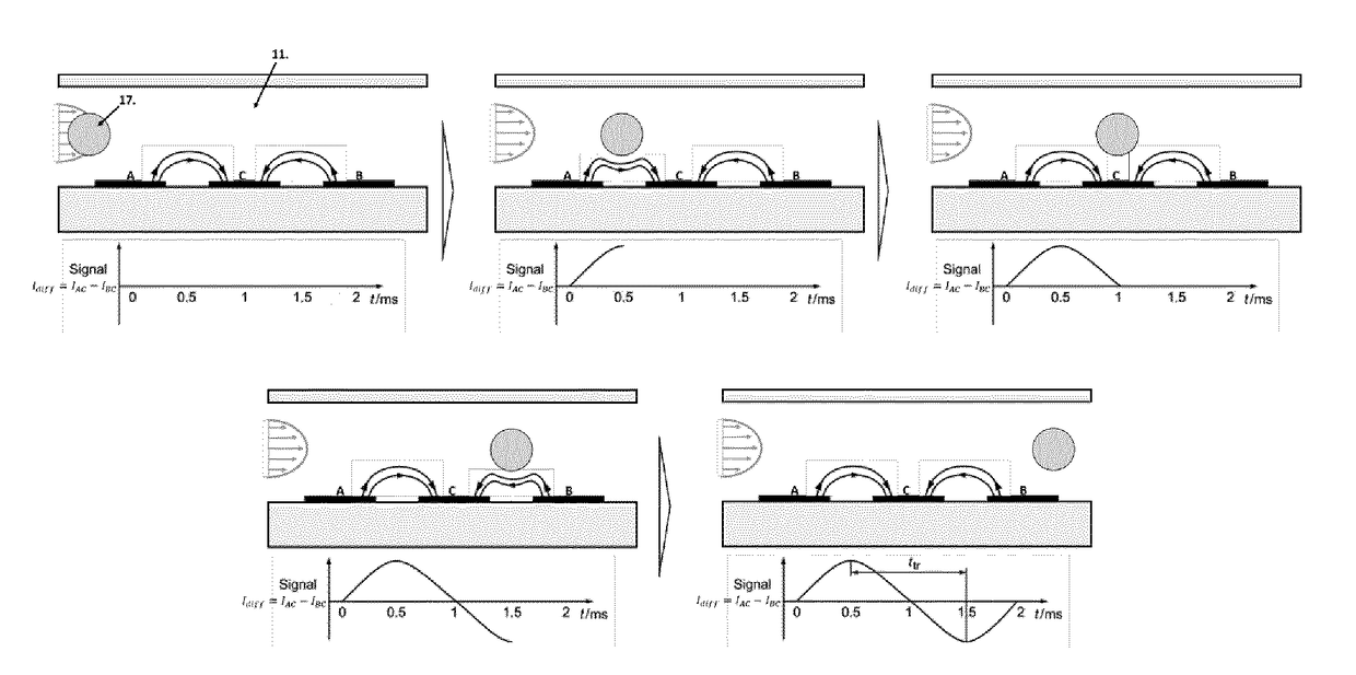
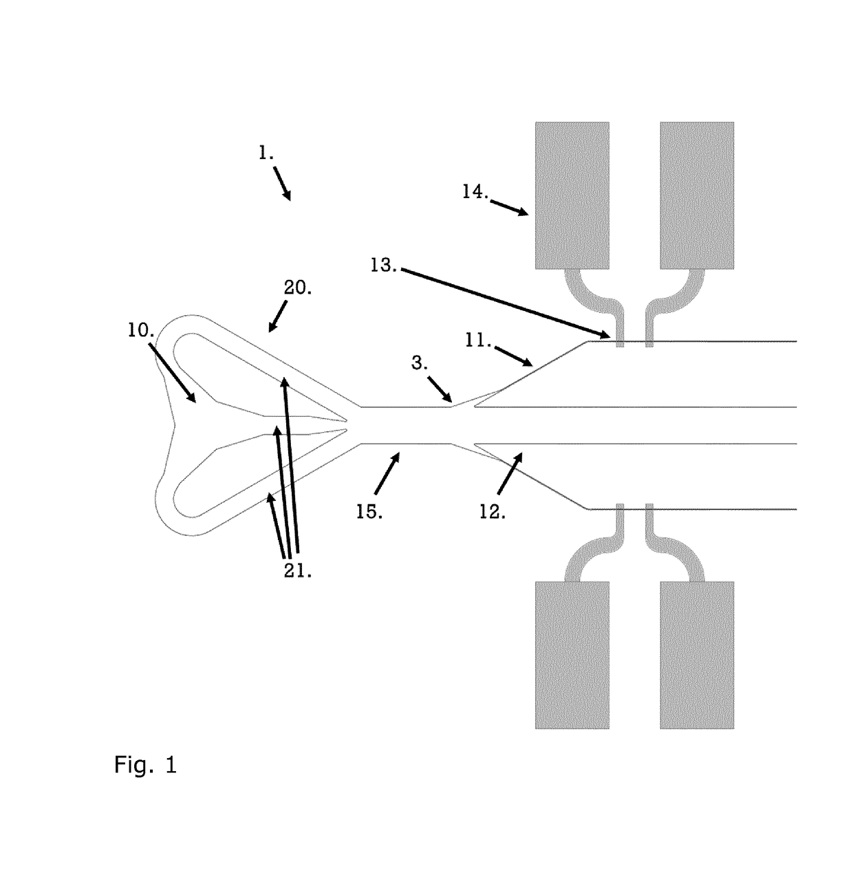
[0120]To demonstrate proof of concept for the use of bypass channels in an impedance flow cytometer, four designs featuring bypass channels and measuring channels were made. The designs were made similar to system depicted in FIG. 1, but with three coplanar electrodes instead of two. The use of three coplanar electrodes allows for an accurate estimate of the transition time, and thus the flow rate, as the 2 μm polystyrene beads follow the laminar flow. The transition time and resulting flow rate was extracted as the peak-to-peak value in the differential measurement, see FIG. 6. The operational principle of differential measurements allows the impedance flow cytometer to be used as a flow sensor if the liquid has particles that follow the flow. The results are summarised in Table 1 and illustrated in FIG. 8.

[0121]Each design had two measuring channels, each with projected Xmeasuring values of 2%, 5%, 10%, and 20%, respectively, for each microfluidic particle analysis device, and a s...

example 2

[0124]A microfluidic particle analysis device as illustrated in FIG. 5 was fabricated as described above to have a bypass channel with a height identical to the height of the measuring channel.

[0125]A microfluidic particle analysis system comprised a coarse filter (pore size 5 μm), a pressure-inducing unit, a flow-splitter, operating electronics, and the microfluidic particle analysis device. The flow splitter was introduced to increase the flow rate prior to the sample entering the microfluidic particle analysis device. The microfluidic particle analysis device was tested by introducing water to the inlet, and thereby to the measuring channel, and measuring a non-differential current. This value can be used to determine if there is water in the channel or not. Further functionality of the chip can be tested by introducing a known quantity of polystyrene beads (either 1 or 2 μm) and subsequently flushing the device to ensure it is clean and ready for operation, e.g. as outlined in E...

example 3

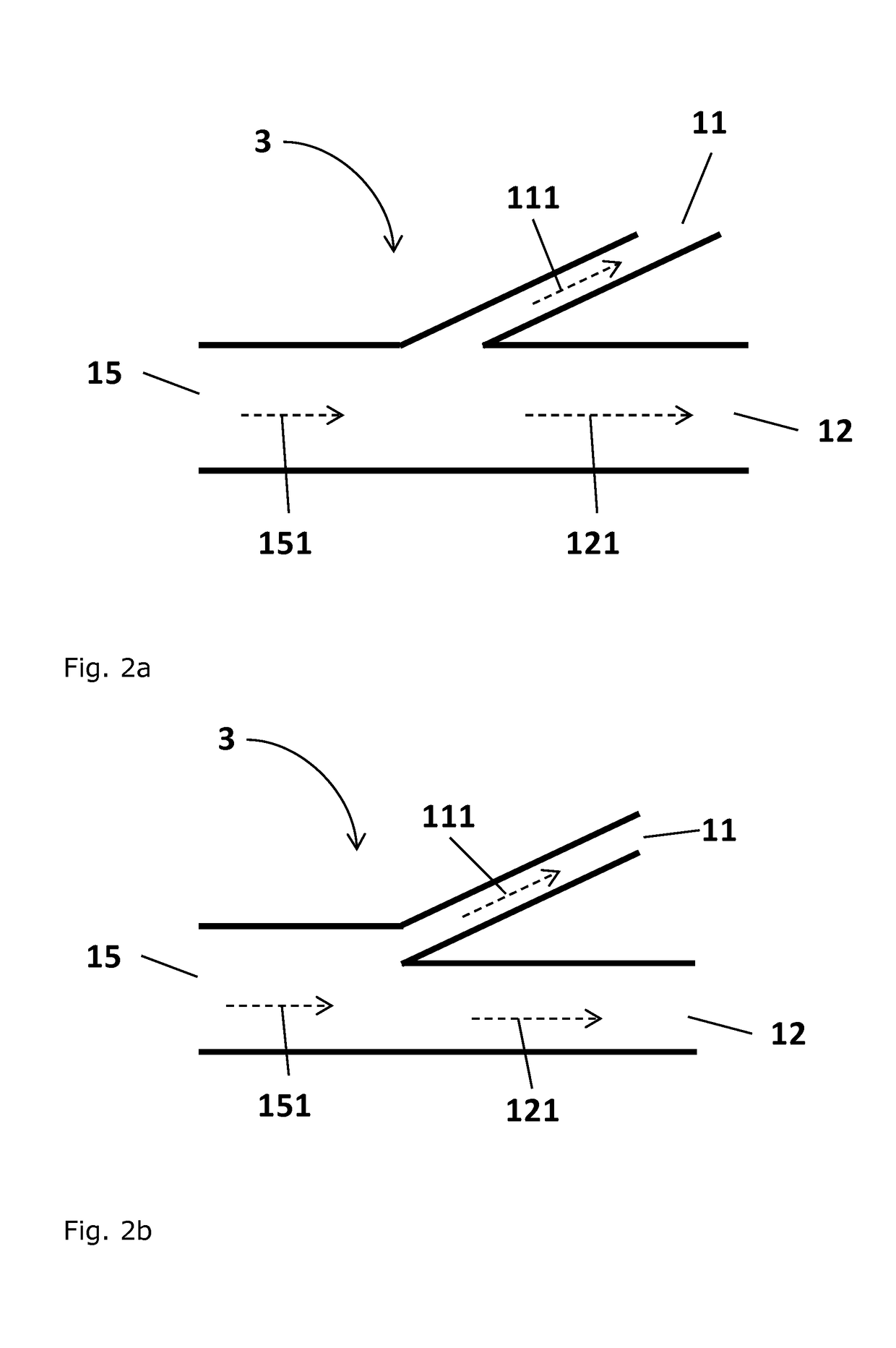
[0126]A microfluidic particle analysis device as illustrated in FIG. 5 was fabricated. The microfluidic particle analysis device had a bypass channel 12 of approximately 1800 μm length and a width of 500 μm. The length of the measuring channel 11 was about 1920 μm, and its width was 10 μm. The length of the main channel 15 was about 19,200 μm and its width was about 500 μm. All channels had a depth of 10 μm. The angle between the bypass channel 12 and the measuring channel 11, and thereby the angle of the measuring channel relative to the main flow direction, was about 30°. Xmeasuring for this device was 0.008.

[0127]For comparison a device was manufactured where the angle between the bypass channel and the measuring channel was 90° (not shown). This device differed from the device of FIG. 5 and described above by having a measuring channel of about 1320 μm length and 10 μm width, a bypass channel with a length of about 1090 μm and a width of 500 μm, a main channel length of 19,800 μ...


PUM


Abstract

The present invention relates to a microfluidic particle analysis device comprising an inlet in fluid communication via a main channel defining a main flow direction with an inlet manifold providing parallel fluid communication with
    • a bypass channel of hydrodynamic resistance Rbypass, and
    • a measuring channel of hydrodynamic resistance Rmeasuring, the measuring channel having a cross-sectional dimension in the range of from 1 μm to 50 μm and further having a sensor system for detecting a particle,
    • wherein a flow distribution parameter Xmeasuring=Rmeasuring−1(Rmeasuring−1+Rbypass−1)−1 is in the range from 10−6 to 0.25, wherein the angle of the measuring channel relative to the main flow direction is in the range of 0° to 60°, and wherein the angle of the bypass channel relative to the main flow direction is in the range of 0° to 60°, and
    • the microfluidic particle analysis device further comprising an outlet in fluid communication with the bypass channel and the measuring channel. The present invention relates to a method of using the device microfluidic particle analysis.

Description

FIELD OF THE INVENTION[0001]The present invention relates to a microfluidic particle analysis device and to a method of detecting a particle in a fluid using the microfluidic particle analysis device. The device is useful for detecting and quantifying bacteria in drinking water, industrial process streams and in other liquids of similar viscosity.PRIOR ART[0002]Analysis of drinking water is a field where no sufficiently fast technologies currently exist that allow detection of harmful bacteria in drinking water in order to prevent pollution of water supplies to households. Current bacteria tests typically require incubation which means that the fastest tests take at least 24 hours to provide results. Analysis methods that can give an indication of the bacteria level in a couple of hours do exist, but they do not provide exact quantitative results. In all cases, manual extraction is required and extracted samples must be sent to a laboratory. This severely limits the testing frequenc...

Claims


Application Information

Patent Timeline
IPC IPC(8): G01N15/10G01N15/06G01N1/20
CPCG01N15/1031G01N1/2035G01N2001/2064G01N15/0656G01N15/1056G01N15/10G01N2015/1075
Inventor SKANDS, GUSTAV ERIKBERTELSEN, CHRISTIAN VINTHER
Owner SBT INSTR AS
Why Eureka
Try Eureka