
Electric power conversion device

a technology of electric power conversion and conversion device, which is applied in the direction of electric variable regulation, process and machine control, instruments, etc., can solve the problems of reducing the efficiency reducing the cost of electric power conversion devices, and reducing the cost of electric power conversion devices. , to achieve the effect of reducing the cost of electric power conversion, and quick convergence ringing

Inactive Publication Date: 2018-01-04
TOYOTA JIDOSHA KK
View PDF5 Cites 4 Cited by
  • Summary
  • Abstract
  • Description
  • Claims
  • Application Information

AI Technical Summary

Benefits of technology

The patent is about a method to control the ringing of a circuit that filters electrical power. By adjusting the capacitance, inductance, and resistance of the circuit, the resonance frequency can be made to match the ringing frequency. This allows for quicker convergence of ringing. Additionally, the approach described makes it easy to select the elements of the circuit that help to pass through the ringing. Overall, this method creates a more effective electric power conversion device with a snubber circuit that suppresses ringing.

Problems solved by technology

In recent years, with improvement of a switching speed of a transistor, suppression of a surge voltage at the time of switching of the transistor becomes an issue.

Method used


Image

  • Electric power conversion device
  • Electric power conversion device
  • Electric power conversion device

Examples


Embodiment Construction

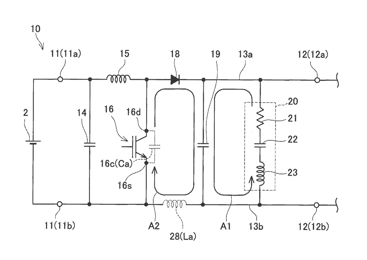
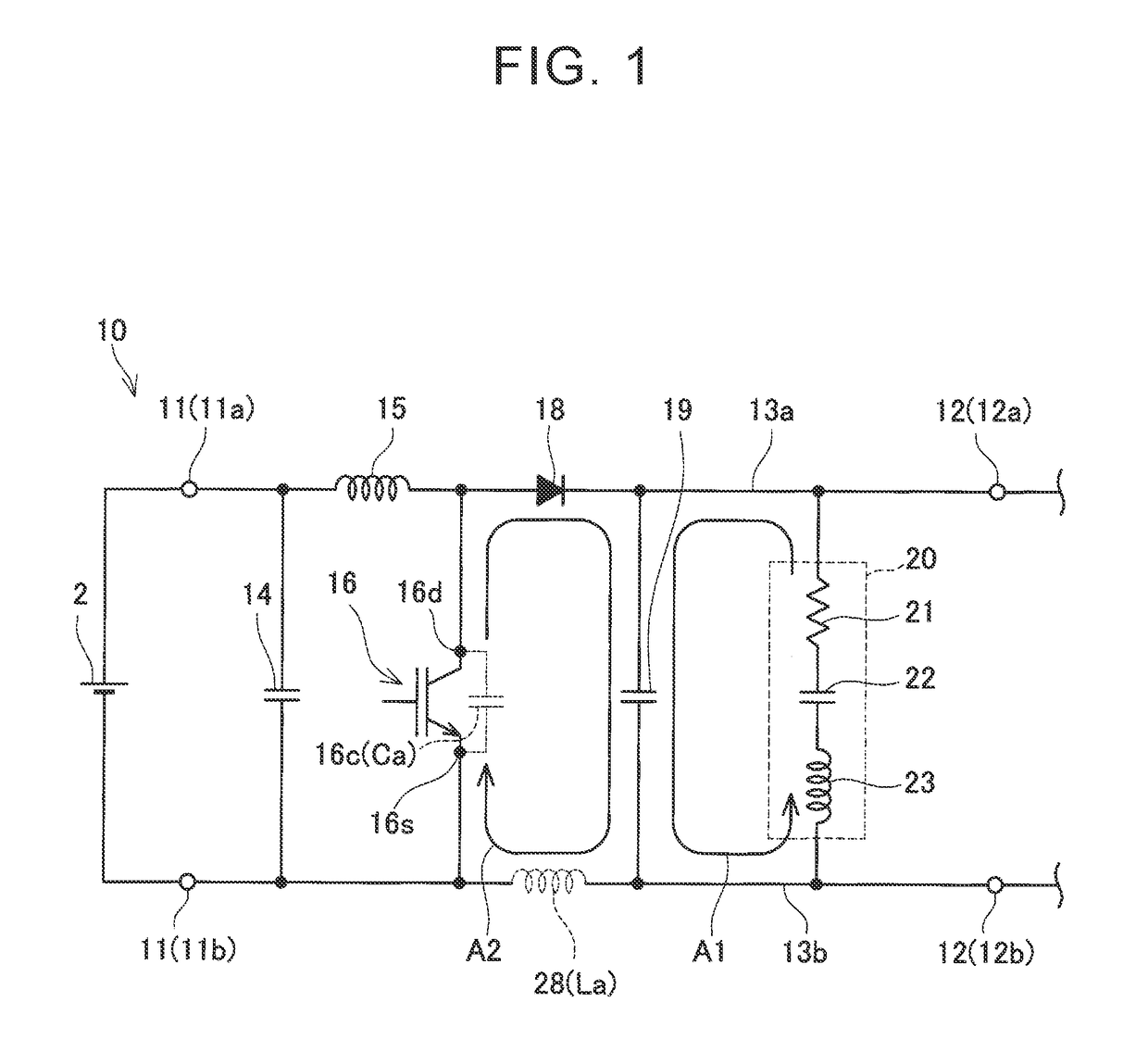
[0018]An electric power conversion device of a first example will be described referring to FIGS. 1 to 4. FIG. 1 is a block diagram of the electric power conversion device of the first example. The electric power conversion device of the first example is a boost converter 10 which boosts the electric power of a direct-current power supply 2 connected to an input end 11 and outputs electric power to an output end 12.

[0019]The circuit structure of the boost converter 10 will be described. The boost converter 10 is provided with a filter capacitor 14, a reactor 15, a transistor 16, an anti-backflow diode 18, a smoothing capacitor 19, and a snubber circuit 20. The transistor 16 is a power transistor for electric power conversion. The transistor 16 is formed with a substrate of silicon carbide (SiC) or gallium nitride (GaN), and has a fast switching speed.

[0020]The filter capacitor 14 is connected between an input end positive electrode 11a and an input end negative electrode 11b of the ...


PUM


Abstract

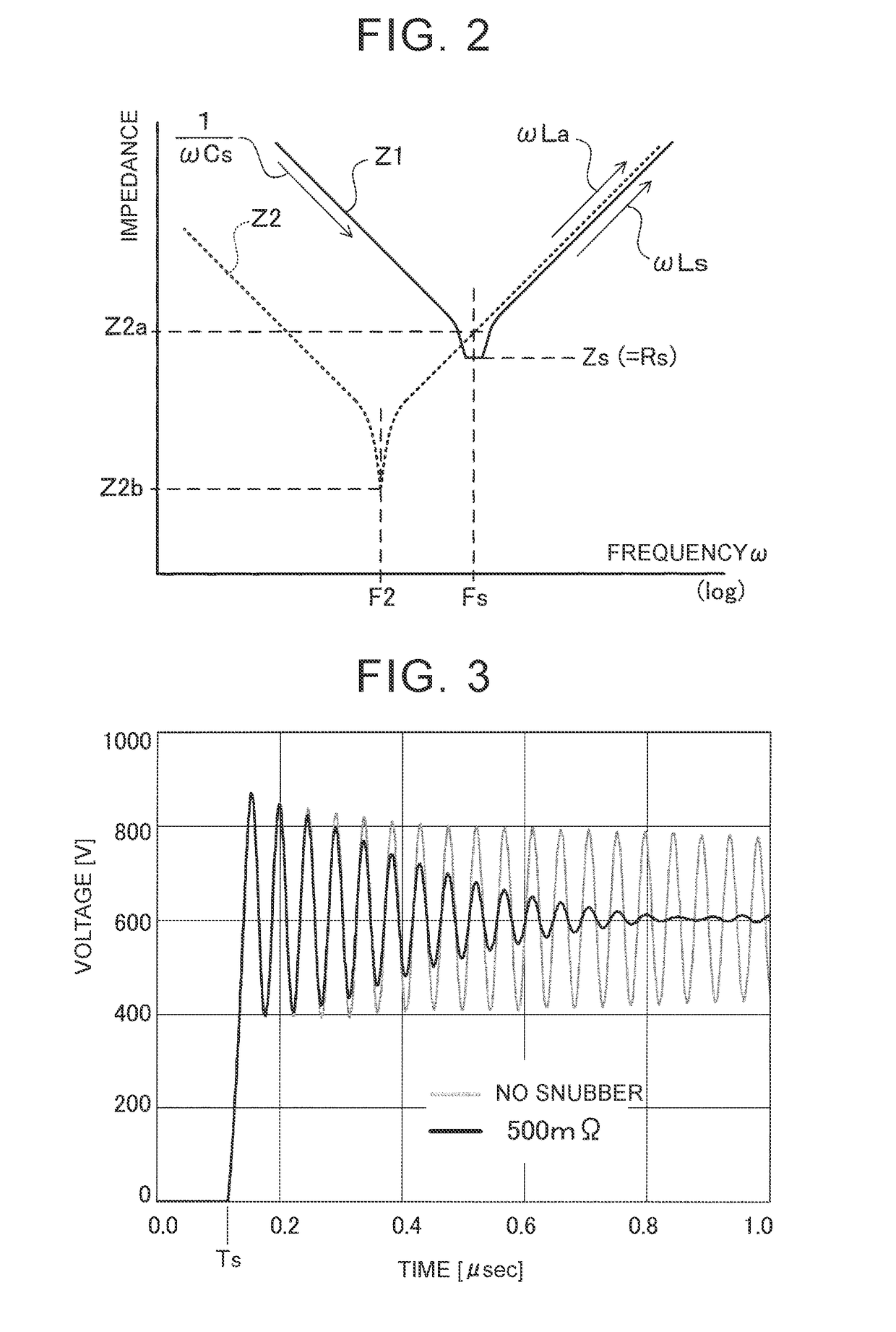
If the capacitance of a snubber capacitor, the inductance of a coil and the magnitude of a resistor are specified such that the resonance frequency of the snubber circuit coincides with the ringing frequency of the transistor, and the impedance of the first loop at the resonance frequency becomes smaller than the impedance of the second loop at the resonance frequency, a current component due to ringing flows in the snubber circuit, and energy is consumed by the resistor. Therefore, it is possible to quickly converge ringing.

Description

INCORPORATION BY REFERENCE[0001]The disclosure of Japanese Patent Application No. 2016-130452 filed on Jun. 30, 2016 including the specification, drawings and abstract is incorporated herein by reference in its entirety.BACKGROUND1. Technical Field[0002]A technique disclosed in this specification relates to an electric power conversion device in which a transistor for electric power conversion and a smoothing capacitor are connected in parallel.2. Description of Related Art[0003]In an electric power conversion device, such as a voltage converter or an inverter, a transistor (power transistor) for electric power conversion is connected between a positive electrode line and a negative electrode line which transmit direct-current electric power, and a smoothing capacitor is further connected between the positive electrode line and the negative electrode line. The smoothing capacitor is provided to suppress ripples (voltage / current impulse) which occur due to repetition of on and off of...

Claims


Application Information

Patent Timeline
IPC IPC(8): H02M1/34H02M3/156H02M1/14
CPCH02M1/34H02M1/14H02M3/156H02M1/348H02M3/155Y02B70/10H02M3/335
Inventor TORII, KAORUYAMAMOTO, KAZUNARIKAJI, KOSUKEKATO, TAIKIKOJIMA, TAKASHINOMURA, KATSUYAHATTORI, YOSHIYUKI
Owner TOYOTA JIDOSHA KK
Learn More