Power circuit device

a power circuit and circuit technology, applied in the direction of printed circuit aspects, cross-talk/noise/interference reduction, dc-ac conversion without reversal, etc., can solve the problems of electrical noise generated by electronic equipment, noise transmission, and other devices to malfunction, so as to achieve the effect of restricting the flow of noise from the load into the system power supply

Active Publication Date: 2018-01-04
MITSUBISHI ELECTRIC CORP
View PDF5 Cites 16 Cited by
  • Summary
  • Abstract
  • Description
  • Claims
  • Application Information

AI Technical Summary

Benefits of technology

[0014]According to the invention, at least one of a first electrical wire, which connects a positive polarity side of a rectifier circuit and an inverter, and a second electrical wire, which connects a negative polarity side of the rectifier circuit and the inverter, and a ground wire terminal are connected by a conductive plate, thereby forming a loop that can collect noise flowing out from a load, noise propagating from the load propagates to the conductive plate through the ground wire terminal, and noise flowing from the load into a system power supply can be restricted.

Problems solved by technology

Generally, electronic equipment generates electrical noise, and equipment for which a countermeasure is insufficient is a factor in causing various problems.
In particular, electrical equipment that operates on an alternating current power supply is often connected via a shared power supply line, and may experience a malfunction due to noise generated in other electrical equipment, or conversely, cause another device to malfunction due to noise generated in a device of the equipment itself.
As a source of noise, there is a slight electrical discharge in an electrical switch and various kinds of motor caused by a semiconductor such as an inverter, and the like, and weakening of energy generated in the source of noise, and causing transmission in a noise, transmission path to be difficult, are carried out as noise countermeasures.

Method used


Image

  • Power circuit device
  • Power circuit device
  • Power circuit device

Examples


first embodiment

[0034]Hereafter, a first embodiment of the invention will be described.

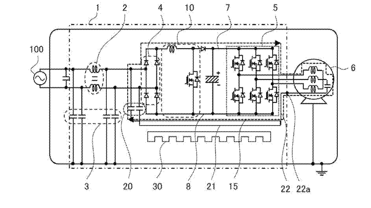
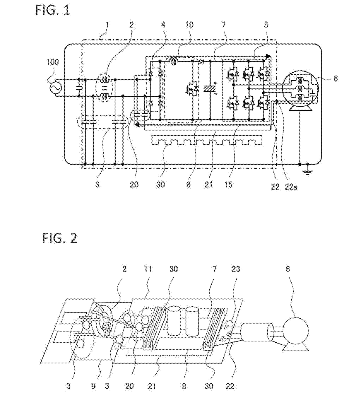
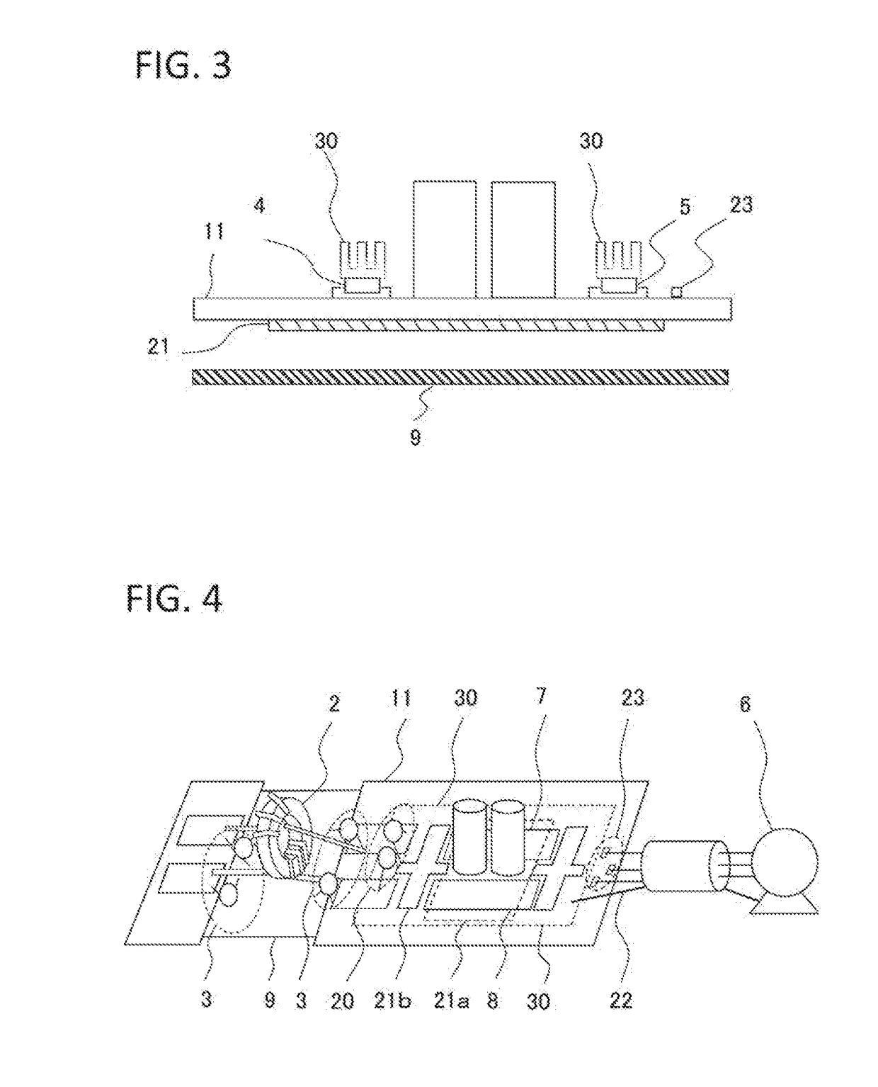
[0035]FIG. 1 is a circuit diagram showing a power circuit device 1 according to the first embodiment of the invention, wherein a system power supply 100 and load 6 connected to the power circuit device 1 are included in FIG. 1. FIG. 2 is a perspective view showing the power circuit device 1 according to the first embodiment of the invention, wherein the system power supply 100 is not shown. FIG. 3 is a side view of a rectifier circuit 4, step-up circuit 10, and inverter 5 portion of the power circuit device 1 according to the first embodiment of the invention.

[0036]As shown in FIG. 1, a grounding capacitor 3 is attached to either end of a common mode coil 2. An upper limit value of capacitance of the grounding capacitor 3, taking leakage current into account, is in the region of 4,700 pF. One common mode coil 2 is connected to the system-power supply 100, while another is connected to the rectifier circuit 4. The...

second embodiment

[0045]Also, when using a part with height, such as an electrolytic capacitor, and disposing the rectifier circuit 4 and inverter 5 on a back surface side of the printed circuit board 11, that is, on the side opposite the surface on which the electrolytic capacitor is provided, a configuration may be such that the conductive plate 21 is configured of a first conductive plate 21a, disposed on the same side as the heatsink 30 with respect to the printed circuit board 11, and a second conductive plate 21b, disposed on the opposite side to the heatsink 30 with respect to the printed circuit board 11, and the first conductive plate 21a and second conductive plate 21b are connected by a via hole 31, as shown in FIG. 4 and FIG. 5.

[0046]According to this configuration, the noise loop 15 can be formed even when using a part with height, such as an electrolytic capacitor, and disposing the rectifier circuit 4 and inverter 5 on the side of the printed circuit board 11 opposite the surface on wh...

third embodiment

[0047]Also, a sandwich structure wherein the first wire 7 and second wire 8 are disposed so as to sandwich the conductive plate 21 from either side, as in FIG. 6, may be adopted. In this case too, the positive polarity side of the rectifier circuit 4 and the first wire 7 are connected, the negative polarity side of the rectifier circuit 4 and the second wire 8 are connected, the positive polarity side of the inverter 5 and the first wire 7 are connected, and the negative polarity side of the inverter 5 and the second wire 7 are connected. Furthermore, in the same way, the positive polarity side of the electrolytic capacitor and the first wire 7 are connected, and the negative polarity side of the electrolytic capacitor and the second wire 8 are connected.

[0048]According to this configuration, the noise loop 15 is configured of the inverter 5, an electrical wire connecting the inverter 5 and load 6, the load 6, the floating capacitance of the load 6, the ground wire terminal 22a, the...


PUM


Abstract

Even when a grounding capacitor is included at either end of a common mode coil, there is noise that flows from a load into a metal frame, and there is a need to restrict an amount of noise propagating to a system power supply. Because of this, a noise loop is formed of a rectifier circuit, an inverter, a first electrical wire that connects a positive polarity side of the rectifier circuit and the inverter, a second electrical wire that connects a negative polarity side of the rectifier circuit and the inverter, a ground wire terminal that can connect a load connected to an output terminal or the inverter, and a conductive plate that connects at least one or the first electrical wire and second electrical wire and the ground wire terminal.

Description

TECHNICAL FIELD[0001]The present invention relates to a power circuit device including an inverter that converts alternating current input from a system power supply into direct current, and subsequently into alternating current again.BACKGROUND ART[0002]Generally, electronic equipment generates electrical noise, and equipment for which a countermeasure is insufficient is a factor in causing various problems. In particular, electrical equipment that operates on an alternating current power supply is often connected via a shared power supply line, and may experience a malfunction due to noise generated in other electrical equipment, or conversely, cause another device to malfunction due to noise generated in a device of the equipment itself.[0003]As a source of noise, there is a slight electrical discharge in an electrical switch and various kinds of motor caused by a semiconductor such as an inverter, and the like, and weakening of energy generated in the source of noise, and causin...

Claims


Application Information

Patent Timeline
Patent Type & Authority Applications(United States)
IPC IPC(8): H05K1/02H02M5/458H05K1/11
CPCH05K1/0231H02M5/458H05K1/0204H05K1/115H05K2201/10015H05K2201/1003H02M7/48H02M1/44H02M1/126H02M7/003H02M1/123H05K1/0218H05K1/0227
Inventor KAMIKURA, MAMORUKATAGIRI, KODAITAKAHASHI, KEITAAKASHI, NORIHIKOHARUNA, NOBUYUKI
Owner MITSUBISHI ELECTRIC CORP
Why Eureka
Try Eureka