Control device of vehicle

a control device and vehicle technology, applied in the direction of electric control, machines/engines, transportation and packaging, etc., can solve the problems of insufficient responsiveness (acceleration responsiveness) of engine output torque, drop in combustion efficiency, etc., and achieve the effect of suppressing nox emission amount and increasing electric motor output torqu

Active Publication Date: 2018-01-11
HONDA MOTOR CO LTD
View PDF0 Cites 9 Cited by
  • Summary
  • Abstract
  • Description
  • Claims
  • Application Information

AI Technical Summary

Benefits of technology

[0016]According to this configuration, when the target air-fuel ratio has been corrected to the limit air-fuel ratio, the electric motor is controlled so as to increase the electric motor output torque by the difference between the output torque of the internal combustion engine and the required torque. Thus, it is possible to suppress the NOx emission amount as well as compensate the insufficiency of the internal combustion engine output torque with the electric motor output torque.

Problems solved by technology

However, performing the exhaust gas recirculation may cause the combustion efficiency to drop (worsen fuel consumption).
However, because the increase of the intake air amount is delayed by the delay in supercharging, the responsiveness (acceleration responsiveness) of the engine output torque tends to be insufficient.

Method used


Image

  • Control device of vehicle
  • Control device of vehicle
  • Control device of vehicle

Examples


first embodiment

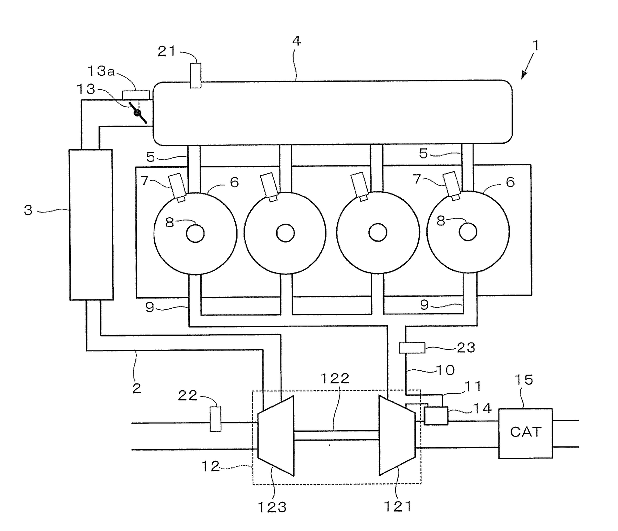
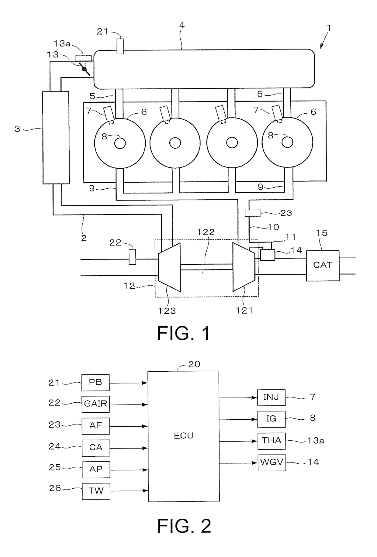
[0028]FIG. 1 is a diagram schematically showing the configuration of a direct injection internal combustion engine for driving a vehicle according to an embodiment of the invention. The vehicle of the present embodiment includes only the internal combustion engine shown in FIG. 1 as the motor. The internal combustion engine (referred to as “engine” hereinafter) 1 has four cylinders 6, and each of the cylinders 6 is provided with an injector 7 and a spark plug 8. The injector 7 injects fuel directly into a combustion chamber of the cylinder 6.

[0029]The engine 1 includes an intake passage 2, an exhaust passage 10, and a turbocharger (supercharger) 12. The intake passage 2 is connected to a surge tank 4, and the surge tank 4 is connected to the combustion chamber of each of the cylinders 6 via an intake manifold 5. The intake passage 2 is provided with an intercooler 3 for cooling pressurized air and a throttle valve 13, and the throttle valve 13 is configured to be driven by a throttl...

second embodiment

[0061]In the present embodiment, the invention is applied to a vehicle that includes the engine 1 and an electric motor as the motor. The second embodiment is the same as the first embodiment except for the following points.

[0062]FIG. 9 schematically shows the overall configuration of a vehicle driving device. The vehicle driving device includes the aforementioned engine 1, an electric motor (referred to as “motor” hereinafter) 61 that functions as the motor and generator, and a transmission 52 for transmitting a driving force of the engine 1 and / or the motor 61. In the vehicle driving device, a crankshaft 51 of the engine 1 is connected to the transmission 52 and is configured to drive a drive wheel 56 via an output shaft 53 of the transmission 52, a differential gear mechanism 54, and a drive shaft 55. The motor 61 is connected to a power drive unit (referred to as “PDU” hereinafter) 62, and the PDU 62 is connected to a high-voltage battery 63. The transmission 52 is a twin clutch...


PUM


Abstract

A control device of a vehicle capable of improving acceleration responsiveness and suppressing increase in the NOx emission amount when a required torque is increased during a steady lean operation. A target air-fuel ratio (AFCMD) is set according to an accelerator pedal operation of a driver. When the driver depresses an accelerator pedal to make an acceleration request during the lean operation, in which the AFCMD is set to a predetermined lean air-fuel ratio (AFLN), air-fuel ratio reduction control is executed to reduce the AFCMD according to the acceleration request. In the air-fuel ratio reduction control, when the AFCMD calculated according to a required torque (TRQCMD) is smaller than a limit air-fuel ratio (AFLMT), the AFCMD is set to the AFLMT, and the AFLMT is set to a value smaller than the AFLN set in a steady state of the lean operation and larger than a theoretical air-fuel ratio (AFST).

Description

CROSS-REFERENCE TO RELATED APPLICATION[0001]This application claims the priority benefit of Japan application serial no. 2016-133010, filed on Jul. 5, 2016. The entirety of the above-mentioned patent application is hereby incorporated by reference herein and made a part of this specification.BACKGROUND OF THE INVENTION[0002]Field of the Invention[0003]The invention relates to a control device of a vehicle that includes an internal combustion engine as the motor, and more particularly relates to a control device for controlling an internal combustion engine that includes a supercharger and performs supercharging during a lean operation, in which an air-fuel ratio of an air-fuel mixture is set to a lean side of a theoretical air-fuel ratio.[0004]Description of Related Art[0005]Patent Literature 1 has disclosed an exhaust gas purification device of an internal combustion engine, which includes a lean NOx catalyst in the exhaust system. According to this device, when it is determined to...

Claims


Application Information

Patent Timeline
Patent Type & Authority Applications(United States)
IPC IPC(8): F02D41/00F02D23/00F02B37/12
CPCF02D41/0007F02B37/12F02D23/00F02D41/10F02D41/1475F02D11/105F02D2250/36F02D29/02Y02T10/12B60W20/00
Inventor TAKEUCHI, MASAHIROUENO, MASAKIHIRONOBU, HIDEKAZUTAKAZAWA, MASANOBUKITANO, HARUYA
Owner HONDA MOTOR CO LTD
Why Eureka
Try Eureka