Photovoltaic Junction Box

a photovoltaic junction box and junction box technology, applied in the direction of circuit thermal arrangement, cooling/ventilation/heating modification, printed circuit details, etc., can solve the problems of poor heat dissipation of plastic and risk, and achieve the effect of increasing the cooling efficiency of the junction box and reducing the size of cooper conductors

Inactive Publication Date: 2018-01-11
CHANGSHU FRIENDS CONNECTOR TECH
View PDF0 Cites 0 Cited by
  • Summary
  • Abstract
  • Description
  • Claims
  • Application Information

AI Technical Summary

Benefits of technology

This patent is about a new design for a junction box used in power distribution systems. The design includes an aluminum heat sink that is mounted on the outer surface of the junction box. The diode module is in close contact with the heat sink, allowing for direct transmission of heat. The aluminum heat sink has high thermal conductivity, which increases the cooling capacity of the junction box. By using metal material instead of plastic material, the junction box is made more resistant to deformation. The design also includes cooper conductors that welded with the diode module provide electrical connection and reduce the size of the junction box. Overall, the new design improves cooling efficiency and enhances safety and reliability of the junction box.

Problems solved by technology

Plastic has poor heat dissipation and is prone to deformation under certain condition, and hence, there is a chance of risk.

Method used


Image

  • Photovoltaic Junction Box
  • Photovoltaic Junction Box
  • Photovoltaic Junction Box

Examples


Embodiment Construction

[0032]As a first preferred embodiment:

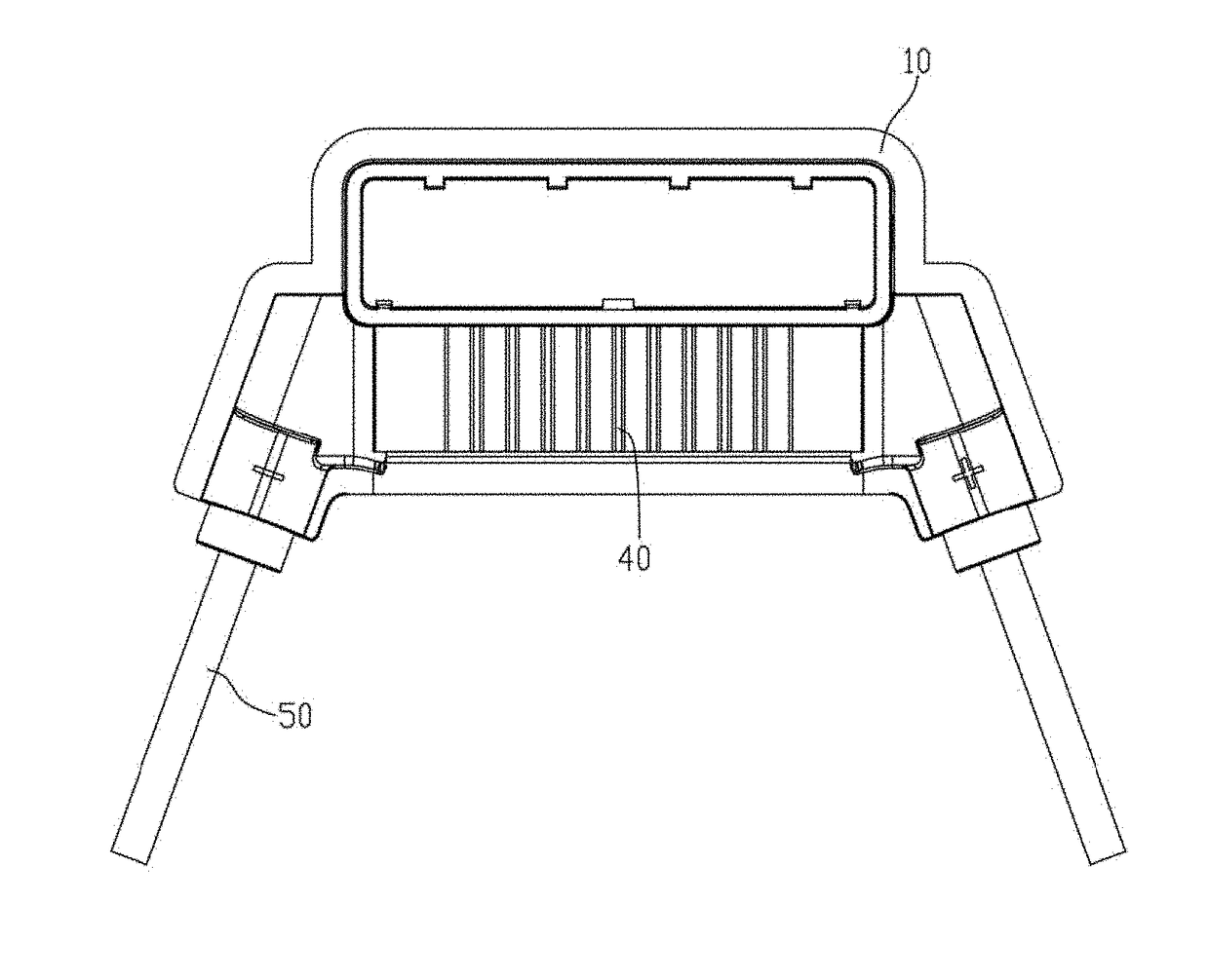
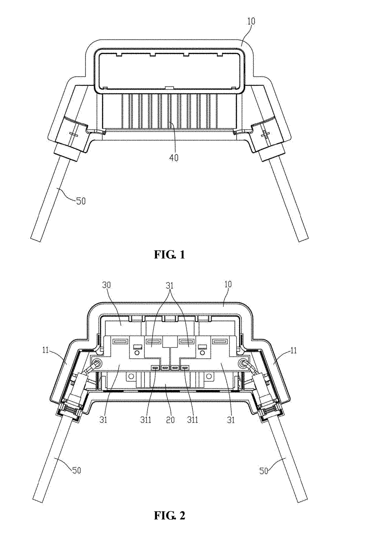
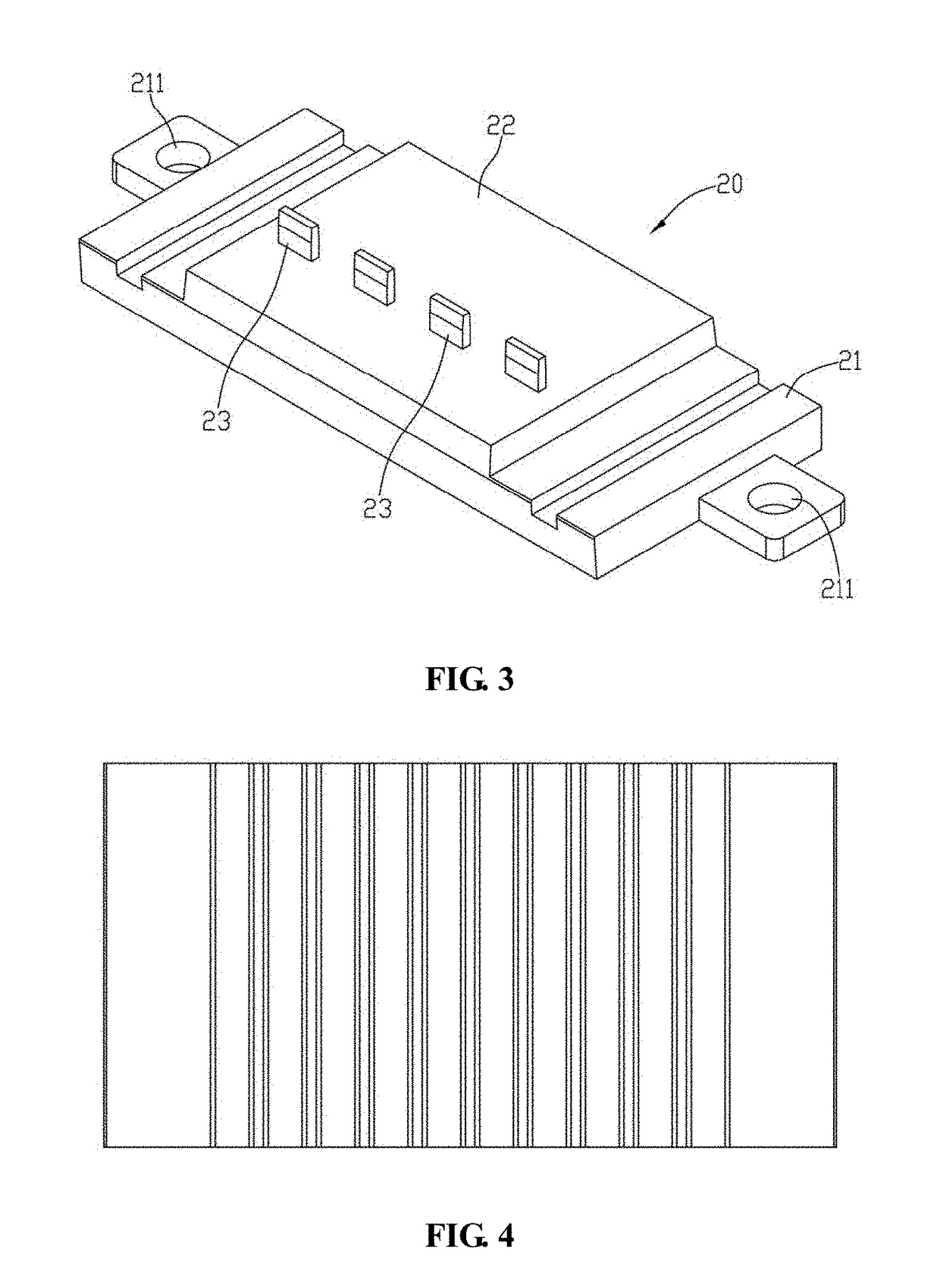
[0033]As shown in FIG. 1 and FIG. 2, a photovoltaic junction box comprising a box body 10, a diode module 20 and a circuit board 30 disposed inside the box body 10, and a heat sink 40 mounted on the outside surface of the box body 10. The circuit board 30 comprising cooper conductors 31 and the diode module 20 is attached to the back side of the heat sink 40 and is electrically connected with cooper conductors 31. As shown in FIG. 3, the diode module 20 comprising a metal back plate 21, an insulating housing 22 and a three diode configuration body. Wherein, welding legs 23 extend from the three diodes to outside the insulting housing 22 and are welded together with the cooper conductors 31, as shown in FIG. 2. The three diodes of the diode module 20 are arranged in a side by side fashion, the number of the cooper conductors 31 equals to the number of the welding legs 23 and the welding legs 23 are also arranged in a side by side fashion. In addi...


PUM


Abstract

A photovoltaic junction box comprising a diode module and a circuit board disposed in a box body, and a heat sink mounted on the outer surface of the box body. The diode module is attached to the back side of the heat sink and is electrically connected to cooper conductor. The heat sink is made of aluminum material and a heat-absorbing layer is provided inside the heat sink. The heat-absorbing layer is close to the diode module. The aluminum heat sink provides great thermal conductivity, therefore, can greatly increase the cooling capacity of the junction box. In addition, because metal material for higher temperature resistance is used instead of lower temperature resistance plastic material, the box body would not deform as easy, greatly increase the safety and reliability of the junction box.

Description

BACKGROUND OF INVENTION1. Field of the Invention[0001]The present invention is related to the technic field of solar energy photovoltaic components, more specifically, a photovoltaic junction box.2. Description of Related Art[0002]Solar energy photovoltaic junction boxes play an important role in the solar energy conversion components. It's main function is to connect the electricity generated from a solar cell to an outside power line. With rapid development of the photovoltaic industry, more and more attention are direct to the junction box, because it not only transmit the electricity generated by the solar cell to the outside power line, at the same time, it also provides the protection for the solar cell components.[0003]The junction box in the current technology uses plastic for it's outer casing. Plastic has poor heat dissipation and is prone to deformation under certain condition, and hence, there is a chance of risk.SUMMARY OF THE INVENTION[0004]The present invention provid...

Claims


Application Information

Patent Timeline
IPC IPC(8): H02S40/34H05K1/02H05K7/20H01R9/24
CPCH02S40/345H05K1/0203H05K7/20427H05K7/20336H01R9/24H02S40/00H02S40/42Y02E10/50
Inventor XU, JIANMING
Owner CHANGSHU FRIENDS CONNECTOR TECH
Why Eureka
Try Eureka