Heartbeat-signal detecting device

a detection device and heartbeat technology, applied in the field of heartbeat signals, can solve the problems of inability to always consider reliable as heartbeat signals, difficult to make clinical evaluations of changes in circulatory system drugs, and difficulty in keeping ecg electrodes attached to the skin for a long time, etc., to achieve rapid medical treatment, improve reliability, and facilitate detection

Active Publication Date: 2018-01-18
NAT UNIV CORP TOKAI NAT HIGHER EDUCATION & RES SYST
View PDF2 Cites 3 Cited by
  • Summary
  • Abstract
  • Description
  • Claims
  • Application Information

AI Technical Summary

Benefits of technology

[0009]In this arrangement, the frequency components, which are in synchronization with the pulse of the heart of the living body superimposed on the respiration signal, are extracted from the respiration signal outputted from the gas-flow calculation controlling portion, by the waveform analysis controlling portion, and the heartbeat signal representing the pulse is outputted. Thus, the heartbeat signal reflecting the ejection action of the heart of the living body can be easily detected by using the heartbeat signal, without using ECG electrodes attached to the living body. That is, the heartbeat signal can be easily obtained even in a case of an infant where it is difficult to keep the ECG electrodes attached to his or her skin for a long time for the purpose of electrocardiograph measurement because the skin is delicate. Further, the heartbeat signal reflecting a cardiac output, i.e., an actual volumetric change of the heart can be obtained, and therefore, as compared with a conventional device using an electrocardiographic induction waveform, it is advantageously possible to confirm the presence or absence of a pulse of the heart with higher reliability, perform quickly a medical treatment at an emergency lifesaving site, and evaluate clinically a circulatory system drug that changes not only a heart rate but also a cardiac output.
[0010]Preferably, the gas-flow sensor may be provided in a trachea, a nasal cavity, outside of the living body or any other position that makes it possible to detect a gas flow of the living body such as exhalation and inhalation. For example, in case of use of an endotracheal intubation tube inserted into the trachea of the living body, the gas-flow sensor is provided in the endotracheal intubation tube or in outside of the living body such as a connection tube interconnecting between the endotracheal intubation tube and an artificial respirator. In case of use of a nasal cannula or a mask disposed to cover a nose and a mouth of the living body, the gas-flow sensor is provided in the nasal cannula, the mask or a connection tube interconnecting between the nasal cannula or mask and an artificial respirator.
[0011]Preferably, the gas-flow sensor is configured to detect a flow speed of the gas passing through a tube, based on a change of an electric resistance of a heater element that is heated by electricity supplied thereto, wherein the electric resistance is changed depending on the flow speed. The heater element is constituted by an electric resistance element whose electric resistance is changed depending on a temperature, wherein the electric resistance is constituted by, for example, a platinum resistance element or a gold resistance element. The heater element is provided on an inner surface of a circuit substrate film which is disposed along an inner wall surface of the tube and which is spaced apart from the inner wall surface by a predetermined space. Further, preferably, a space is provided between the heater and the tube, to insulate heat transmission from the heater to the tube. Owing to this construction, even where the tube is made of a flexible mate...

Problems solved by technology

However, in a case where the patient is an infant, there is a problem that it is difficult to keep the ECG electrodes attached to his or her skin for a long time for the purpose of electrocardiograph measurement because the skin of an infant is delicate.
Further, there is another problem that the electrocardiographic induction waveform does not reflect a cardiac output, i.e., an actual volumetric change of a heart, and the generation of the electrocardiographic induc...

Method used


Image

  • Heartbeat-signal detecting device
  • Heartbeat-signal detecting device
  • Heartbeat-signal detecting device

Examples


embodiment 1

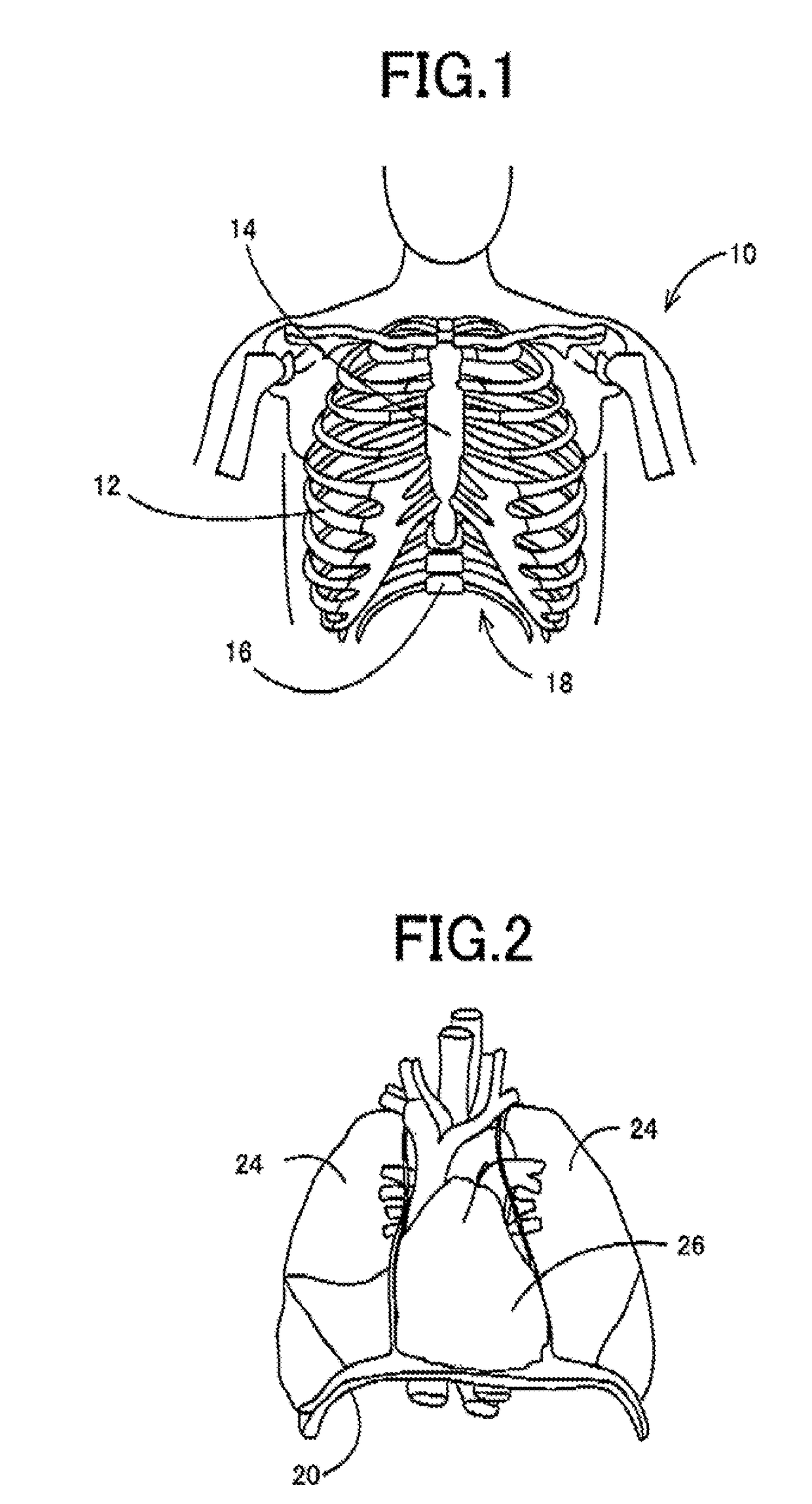
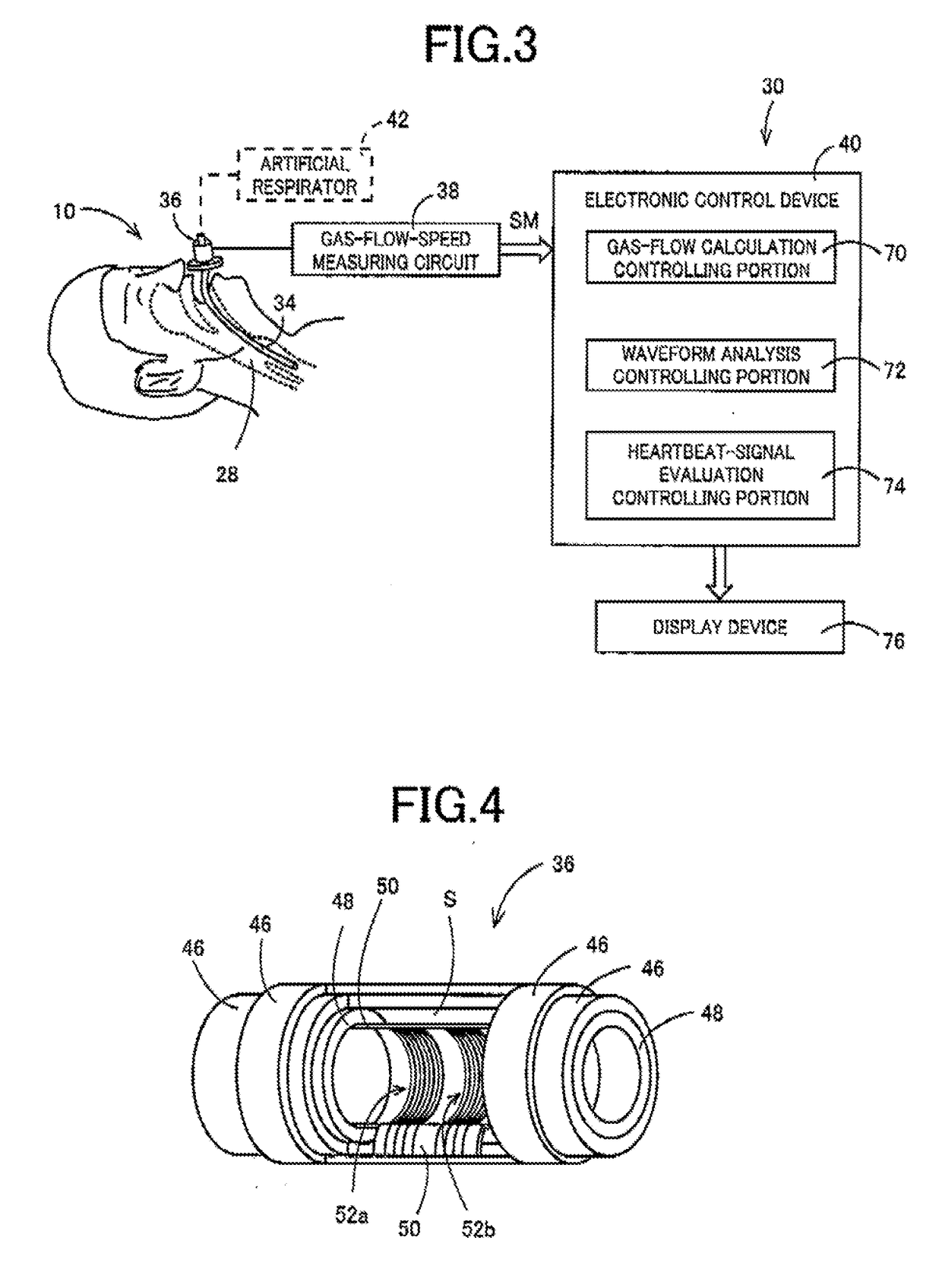
[0067]As shown in FIGS. 1 and 2, in a living body 10, there are accommodated lungs 24 and a heart 26 within a thoracic cavity that is isolated by a thorax 18 having a relatively high rigidity and a thoracic diaphragm 20 closing a lower opening of the thorax 18, wherein the thorax 18 is surrounded by ribs 12, a sternum 14 and thoracic vertebrae 16. Although a volumetric change of the heart 26, which is caused by a pulse, is smaller than a volumetric change of the lungs 24, which is caused by a respiratory motion, the cycle of the volumetric change of the heart 26 is short so that the volumetric change of the heart 26 is clearly superimposed on the ventilatory waveform of the lungs 24. Therefore, attention was paid to a point that, if a respiratory waveform (ventilatory waveform), which represents a flow speed or flow rate of a gas passing through a trachea 28 of the living body 10, is detected, a heartbeat signal can be extracted from the detected respiratory waveform. Hereinafter, i...

embodiment 2

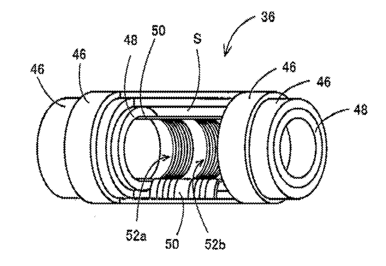
[0089]In the gas-flow sensor 36 in the above-described embodiment, the pair of heater elements 52a, 52b are provided. However, a single heater element may be provided, as shown in FIG. 13. In this case, although the direction of flow of air is not made clear, the gas-flow rate can be measured. FIG. 13 is a perspective view showing the gas-flow sensor 36 having the single heater element 52a, and corresponding to the view of FIG. 4. FIG. 14 is a view showing a resistance change characteristic TCR indicating a rate of change of resistance value of the heater element 52a in relation with temperature, wherein the indicated rate of change is a value relative to 100, which is a value when the temperature is 30° C. FIG. 15 is a view showing a circuit indicating a construction of a gas-flow rate measuring circuit for operating the gas-flow sensor 36 with the single heater element 52a, and corresponding to the view of FIG. 6. As shown in FIG. 15, the gas-flow-speed measuring circuit 38 includ...

embodiment 31

[0090]FIG. 16 shows an example in which a pair of detection resistor elements 53a, 53b are provided on respective opposite sides of the heater element 52a, wherein the detection resistor elements 53a, 53b are configured to measure the flow rate, based on change of the resistance value. In the gas-flow sensor 36 of the present embodiment, the detection resistor elements 53a, 53b are separated from the heater element 52a, so that an accuracy of measurement of the flow rate can be made higher than in the gas-flow sensor 36 having the single heater element 52a. In the present embodiment, for example, the measuring circuit shown in FIG. 6 is connected to the detection resistor elements 53a, 53b, and a heating control circuit is connected to the heater element 52a, for heating the heater element 52a to a constant temperature.


PUM


Abstract

A heartbeat-signal detecting device, which is for detecting a heartbeat signal of a living body, includes: (a) a gas-flow sensor configured to detect a flow rate of exhalation and inhalation passing through a trachea of the living body; (b) a gas-flow calculation controlling portion configured to output a respiration signal that reflects a respiratory motion of the living body, based on a signal outputted from the gas-flow sensor; (c) a waveform analysis controlling portion configured to extract, from the respiration signal, frequency components which are in synchronization with a pulse of a heart of the living body superimposed on the respiration signal, and to output a heartbeat signal representing a heartbeat waveform of the living body; and (d) a heartbeat-signal evaluation controlling portion is configured to evaluate a functional abnormality or an anatomic abnormality of the heart, based on the heartbeat signal analyzed by the waveform analysis controlling portion.

Description

TECHNICAL FIELD[0001]The present invention relates to a heartbeat-signal detecting device which is capable of easily detecting a heartbeat signal reflecting an ejection action of a heart of a living body, more preferably, and which is capable of also evaluating a physiological function of the heart, without using electrodes attached to the living body.BACKGROUND ART[0002]The heartbeat signal of the living body is important information of the living body. Conventionally, there has been used an electrocardiographic induction device that detects, as the heartbeat signal, an electrocardiogram obtained through a plurality of ECG electrodes attached to the living body. For example, devices disclosed in Patent Documents 1 and 2 are examples of such a device. The electrocardiogram is called as electrocardiographic induction waveform or ECG waveform, and R wave contained in the electrocardiogram is characterized to have a considerably clear pulse shape, so as to be easily detectable. Thus, t...

Claims


Application Information

Patent Timeline
IPC IPC(8): A61B5/00A61B5/024A61B5/087G01F1/69A61B1/267
CPCA61B5/7278A61B5/024A61B5/7257A61B5/087A61B5/6803A61B1/2676A61B5/6852G01F1/69A61B1/273A61B5/0245G01F1/68
Inventor KAWABE, TSUTOMUSHIKIDA, MITSUHIROMATSUSHIMA, MIYOKO
Owner NAT UNIV CORP TOKAI NAT HIGHER EDUCATION & RES SYST
Why Eureka
Try Eureka