Additive channels

a technology of additive channels and channels, applied in biochemistry apparatus and processes, laboratories, instruments, etc., can solve the problems of difficult to accurately and reliably assess platelet function, and subject cells to shear stress, so as to prevent blood clotting, prevent coagulation, and amplify the potential spectrum of applications of this anticoagulant

Active Publication Date: 2018-01-18
EMULATE INC
View PDF8 Cites 0 Cited by
  • Summary
  • Abstract
  • Description
  • Claims
  • Application Information

AI Technical Summary

Benefits of technology

[0005]In one embodiment, fixatives are contemplated as additives for the additive channel (which can be useful for capturing the cells and platelets in their state immediately after contact with the cells in the chip). In one embodiment, oil is contemplated as an additive for the additive channel, to form blood-containing droplets (e.g. for sequestering blood samples from different time-points in the run, and analyzing them separately afterwards), etc. The addition of an additive channel near the outlet allows (in a versatile way) quick treatment of blood samples as they leave the chip. Such treated blood samples are contemplated to enable downstream analysis including but not limited to new types of analysis from the use of the additive channel for treating blood components as it leaves the chip.
[0049]Additionally, the term “microfluidic” as used herein relates to components where moving fluid is constrained in or directed through one or more channels wherein one or more dimensions are 1 mm or smaller (microscale). Microfluidic channels may be larger than microscale in one or more directions, though the channels) will be on the microscale in at least one direction. In some instances the geometry of a microfluidic channel may be configured to control the fluid flow rate through the channel (e.g. increase channel height to reduce shear). Microfluidic channels can be formed of various geometries to facilitate a wide range of flow rates through the channels.

Problems solved by technology

Indeed, part of the reason why it has been difficult to assess platelet function accurately and reliably in vitro could be due to the fact that the existing tests do not incorporate a relevant shear stress environment or assess the contribution of endothelial function.
Such devices subject the cells to shear stress.

Method used


Image

  • Additive channels
  • Additive channels
  • Additive channels

Examples


example 1

Materials And Methods

[0299]This example describes exemplary materials and methods used during the development of the present inventions.

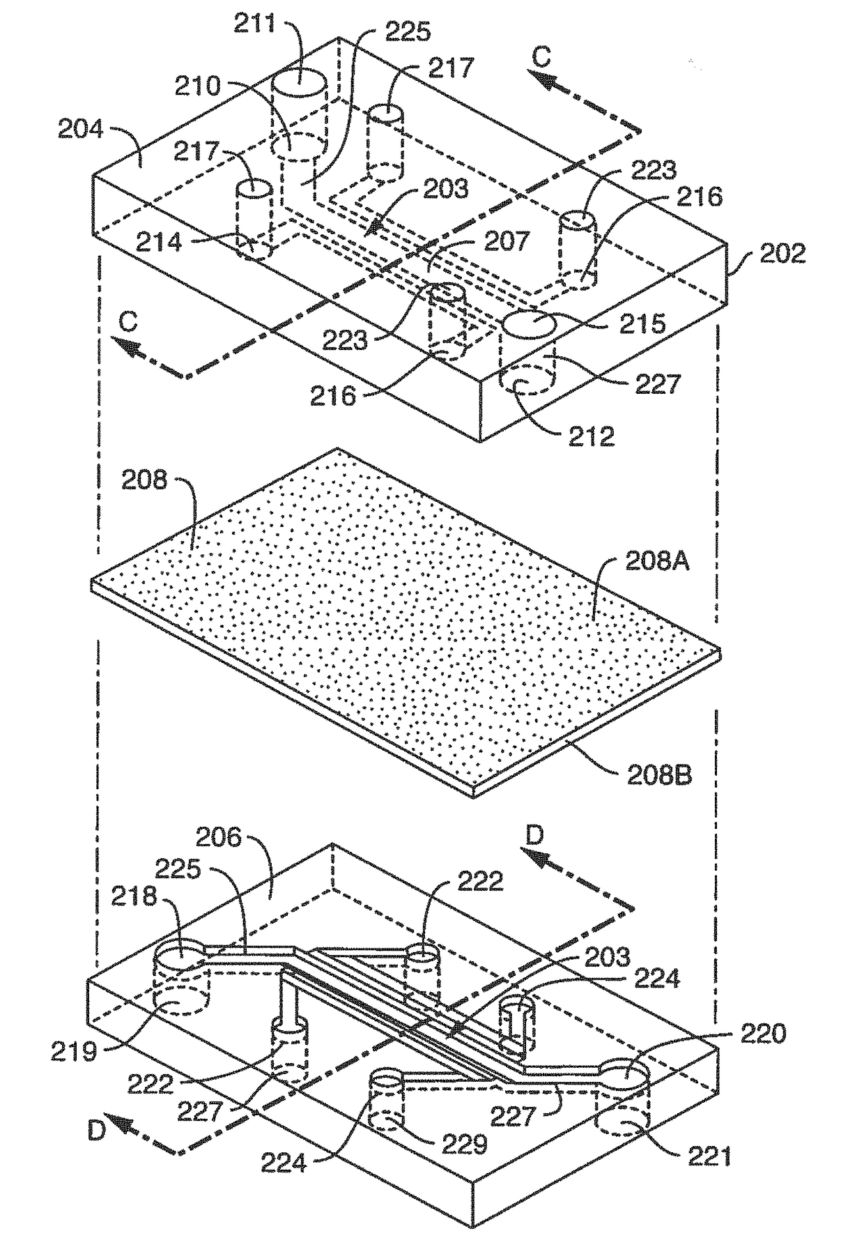
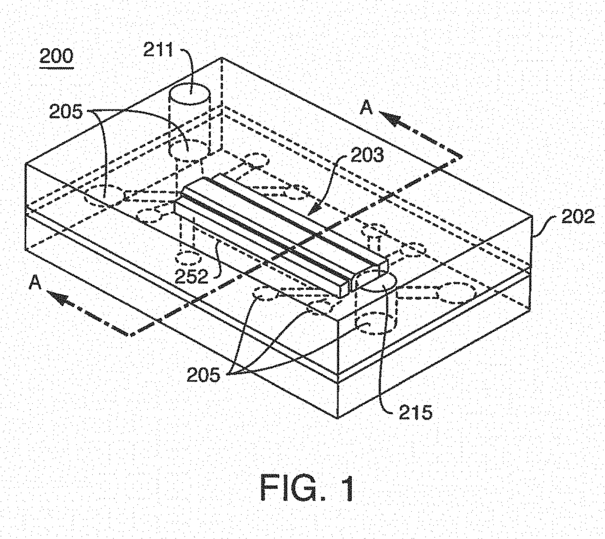
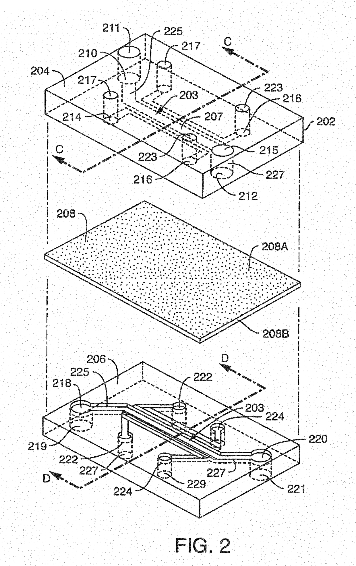
[0300]Microfluidic Chip Manufacturing And Surface Activation; Chip design and fabrication as used herein, were initially modified versions of previously described chips (See, Huh, D. el al. Microfabrication of human organs-on-chips, Nat Protoc. 8:2135-2157 (2013). In further embodiments, chip designs used herein and contemplated chip designs are unlike previously published chips.

[0301]In one embodiment, the surface area of the vascular compartment of a microfluidic chip used herein is greater in comparison to the original lung-on-a-chip design because the original size was too small for optimal blood component interaction with endothelium. As described herein, a 1 mm wide and 200 um tall chamber provided an increase in size of the vascular surface area exposed to laminar flow, as compared to an exemplary lung-on-chip. An anticoagulant port, referred...

example 2

Endothelial cells control clotting in the Vessel-On-Chip

[0325]This example describes exemplary clotting on the chip that is controlled by endothelial cells.

[0326]sCollagen treatment of blood activates blood components while endothelial pre-treatment with TNF-α mimics (simulates) tissue inflammation. Therefore, sCollagen treated blood was added to a Vessel-On-Chip containing TNF-alpha pre-treated endothelial cells (endothelium), for simulating inflammation.

[0327]More specifically, INF-α (50 ng / ml) was added to a Vessel-On-Chip for contact with the endothelium for 6 hours of incubation. Soluble collagen (sCollagen), a standard platelet activator, was used at 10 μg / ml for treating blood samples, either prior to adding to a Vessel-On-Chip or through an additive channel attached to an intake port as the blood sample is being added to the intake port.

[0328]The use of TNF-α or sCollagen treatments on thrombosis in a Vessel-On-Chip led to more aggressive patterns of platelet aggregation and...

example 3

Testing The Use Of An Additive Channel In A Vessel-On-Chip For On-Chip Biomarker Assessment And Treatment With A Candidate Drug

I. Additive Channel

[0331]In order to functionally test the additive channel (i.e. microfluidic chamber(s)) attached to the outflow port of a Vessel-On-Chip, re-calcified blood was perfused through the inlet port while citrate was introduced online from a port situated next to the outflow port, flowing through the additive channel. Thus, blood obtained from the effluent of chips equipped with the anticoagulant port (additive channel) or without anticoagulant port were compared (FIG. 6). From a qualitative point of view the difference was striking. Introduction of sodium citrate through the anticoagulant port allowed for collection of soluble (not clotted) blood at the end of each experiment that remained in the liquid status (FIG. 6).

II. Vessel-On-Chip Biomarker Assessment

[0332]Blood sampled from the Vessel-On-Chip outflow port was analyzed for thrombin anti-...


PUM

PropertyMeasurementUnit
lengthaaaaaaaaaa
lengthaaaaaaaaaa
diameteraaaaaaaaaa

Abstract

Compositions, devices and methods are described for preventing, reducing, controlling or delaying adhesion, adsorption, surface-mediated clot formation, or coagulation in a microfluidic device or chip. In one embodiment, blood (or other fluid with blood components) that contains anticoagulant is introduced into a microfluidic device comprising one or more additive channels containing one or more reagents that will re-activate the native coagulation cascade in the blood that makes contact with it “on-chip” before moving into the experimental region of the chip.

Description

FIELD OF THE INVENTION[0001]The present invention contemplates compositions, devices and methods of preventing, reducing, controlling or delaying adhesion, adsorption, swine-mediated clot formation, or coagulation in a microfluidic device or chip. In one embodiment, blood (or other fluid with blood components) that contains anticoagulant is introduced into a microfluidic device comprising one or more additive channels containing one or more reagents that will re-activate the native coagulation cascade in the blood that makes contact with it “on-chip” before moving into the experimental region of the chip.BACKGROUND[0002]Blood clotting, a process that relies on adhesion of platelets and proteins to a surface as a first step, can be a problem when blood is introduced into a microfluidic device. Undesired clot formation can make many desired blood tests impossible. Heparin coating of surfaces can control blood clotting to a limited extent. See Barstad, R. M, et al., Thrombosis and Haem...

Claims


Application Information

Patent Timeline
Patent Type & Authority Applications(United States)
IPC IPC(8): B01L3/00G01N33/86
CPCB01L3/502715B01L3/502761B01L3/502746G01N33/86G01N2500/10B01L2200/16B01L2300/0887B01L2300/0816B01L2300/0867B01L3/502707B01L2200/027B01L2200/0647B01L2300/0883B01L2300/14B01L2300/16C12M23/16C12M29/04C12M29/10C12M35/08C12M41/46G01N33/54366B01L3/5027C12M3/00G01N33/49G01N33/4905G01N33/543B01L3/5023B01L2200/02B01L2200/0605B01L2300/0809C12M29/00G01N33/80
Inventor LEVNER, DANIELHINOJOSA, CHRISTOPHER DAVIDWEN, NORMANFRASER, JACOBNGUYEN, JUSTINBARRILE, RICCARDOHAMILTON, GERALDINEKARALIS, CATHERINEPARK, HYOUNG SHINVARONE, ANTONIOVAN DER MEER, ANDRIESOTIENO, MONICACONEGLIANO, DAVID
Owner EMULATE INC
Why Eureka
Try Eureka