Brush for cosmetic implements and manufacturing method of the same

a technology for cosmetic implements and brushes, which is applied in the direction of packaging foodstuffs, packaging goods, transportation and packaging, etc. it can solve the problems of uneven length of bristles (tip parts), inconvenient user application of mascara to eyelashes, and additional problems such as increasing the radius of support members, so as to achieve convenient formation

Inactive Publication Date: 2018-01-25
MITSUBISHI PENCIL CO LTD
View PDF4 Cites 0 Cited by
  • Summary
  • Abstract
  • Description
  • Claims
  • Application Information

AI Technical Summary

Benefits of technology

[0023]The manufacturing method includes the steps of bundling the synthetic resin fibers to provide a brush part on the support member; immersing the brush part in a solution bath in which a soluble liquid is contained; moving the brush part up and down from an upper side of a polishing / rubbing blade; causing the brush part to come into contact with a polishing / rubbing blade for a predetermined time; dissolving and swelling a surface of the synthetic resin fiber; and scrubbing off the surface of the synthetic resin fiber by the polishing / rubbing blade, to form the tapered surface, and therefore the tapered surface is easily formed to the bristles provided on the circumferential surface of the support member. The present invention can provide the brush for cosmetic implements provided with bristles having tapered tip ends on a circumferential surface of the support member and the manufacturing method of the brush.

Problems solved by technology

Accordingly, it is inconvenient to users to have to apply mascara to the eyelashes while paying attention to the position of the brush part.
To eliminate such an inconvenience, it is possible to insert the plural brush parts around all the circumference of the support member, but this raises an additional problem to increase the radius of the support member.
Another method is to implant tapered bristles at plural positions on the circumferential surface of the axial direction by fusing or adhesion, but this further causes to make the length of the bristles (tip part) uneven.
As described above, forming the tip ends of the bristles (fibers) to have a conical shape is difficult by tapering with whetstones or files, and tapering with thermal processing may adversely cause the bristles to fuse to each other.

Method used


Image

  • Brush for cosmetic implements and manufacturing method of the same
  • Brush for cosmetic implements and manufacturing method of the same
  • Brush for cosmetic implements and manufacturing method of the same

Examples


Embodiment Construction

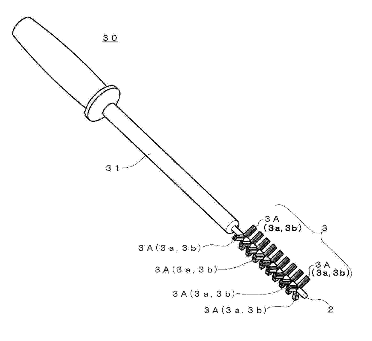
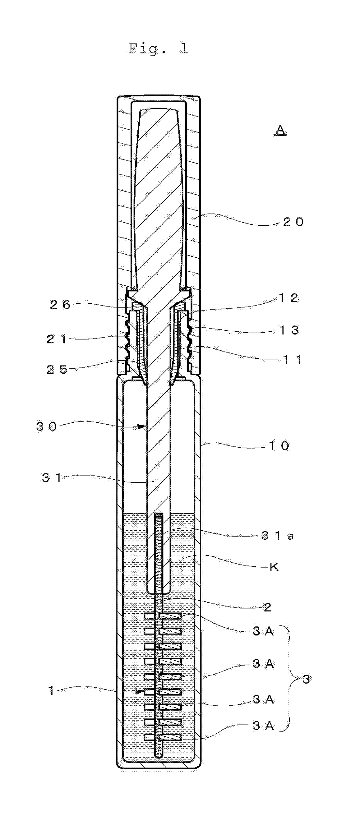
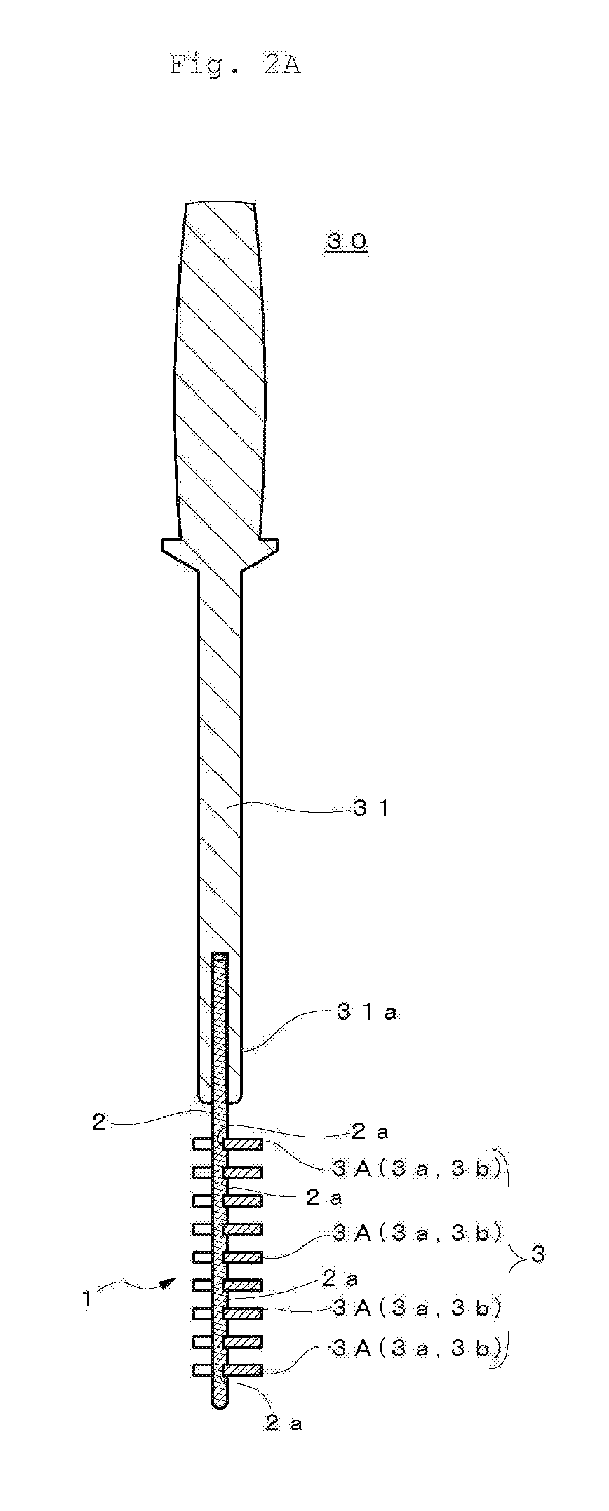
[0037]Hereinafter, an explanation will be made of an embodiment of the present invention with reference to the drawings FIGS. 1 through 5. Cosmetic implements to which the brush according to the present invention is utilized are such as eye-liners, mascaras, nail polish, lipsticks, hair dyes. In the present embodiments, a mascara having fluidity will be described as an example. A cosmetic implement A includes a container 10 containing a coating liquid K, a cap 20 threadedly engaging with the container 10, and applicator 30 provided with a brush part 3 immersed in the coating liquid K in the container 10.

[0038]The container 10 is formed in a bottomed cylinder shape having a neck portion 11 and contains a prescribed amount of the coating liquid K of mascara with fluidity. The coating liquid includes, as disclosed in Japanese Patent No. 5791424, a viscosity modifier 0.1 to 2 wt %, a film-forming agent 0.5 to 30 wt %, a pigment having an average diameter 1 mm or larger 0.5 to 30 wt %, d...


PUM


Abstract

A brush for cosmetic implements includes a brush part attached to a support member; the brush part includes a plurality of synthetic resin fibers whose tip end has a conically tapered surface, and a plurality of fiber bundles composed of a plurality of synthetic resin fibers is formed at least three places in a radial circumferential surface of the support member, and further formed in an axial direction of the support member. Provided is a brush for a cosmetic implements in which a brush bristle having a tapered end is provided around the support member in the radial direction, and a manufacturing method thereof.

Description

BACKGROUND OF THE INVENTIONField of the Invention[0001]The present invention relates to brushes for cosmetic implements and a manufacturing method of the same. More specifically the invention relates to brushes for cosmetic implements such as a mascara brush, having bristles that extends in radial directions of the support member, perpendicular to the axis thereof and a manufacturing method of the same.Description of Related Art[0002]As a brush for cosmetic implements having bristles that extends in radial directions of the support member, perpendicular to the axis thereof, a mascara brush, for example, to apply mascara onto eyelashes is known. In this mascara brush, for example, a large number of the brush bristles are fixed between two twisted wires such that the bristles extend from the wires (the axis) in radial directions, perpendicular to the axis. In addition, some brushes have bristles (fibers), free ends of which are formed to be tapered, and are capable of easily entering ...

Claims


Application Information

Patent Timeline
Patent Type & Authority Applications(United States)
IPC IPC(8): A45D40/26A46B9/02A46B7/00
CPCA45D40/262A46B7/00A46B3/00A46B2200/1046A45D33/00A46B9/021A46D1/0207A46D1/0253A46D1/0276A46D1/05A46B2200/106A46B2200/1053A46B3/18A46D1/04A46D1/08
Inventor NAKAMURA, HITOSHITAKIGAWA, SEIICHI
Owner MITSUBISHI PENCIL CO LTD
Why Eureka
Try Eureka