Plasma spectroscopic analysis method and plasma spectroscopic analyzer

a plasma spectroscopic analyzer and analysis method technology, applied in material analysis, instruments, testing metals, etc., can solve the problems of low analytical sensitivity, difficult measurement, and variability in analysis, and achieve suppressed occurrence of analytical errors in sample analysis. , the effect of high analytical sensitivity

Inactive Publication Date: 2018-01-25
ARKRAY INC
View PDF1 Cites 1 Cited by
  • Summary
  • Abstract
  • Description
  • Claims
  • Application Information

AI Technical Summary

Benefits of technology

[0021]According to the plasma spectroscopic analysis method in the present disclosure, a high analytical sensi

Problems solved by technology

However, in the method of JP-A No. 2009-128315, there was a problem that, without a proper pretreatment, contamination of the sample with other substances caused variations in the analysis results.
Further, in the methods of JP-A No. 2011-180045 and JP-A No. 2012-185064, when a sample containing impurities is used or when foreign substances and the like

Method used


Image

  • Plasma spectroscopic analysis method and plasma spectroscopic analyzer
  • Plasma spectroscopic analysis method and plasma spectroscopic analyzer

Examples


example 1

[0088]It was verified that the analysis method according to the present disclosure is capable of analyzing lead contained in urine specimens with only small variations over a wide range of concentration.

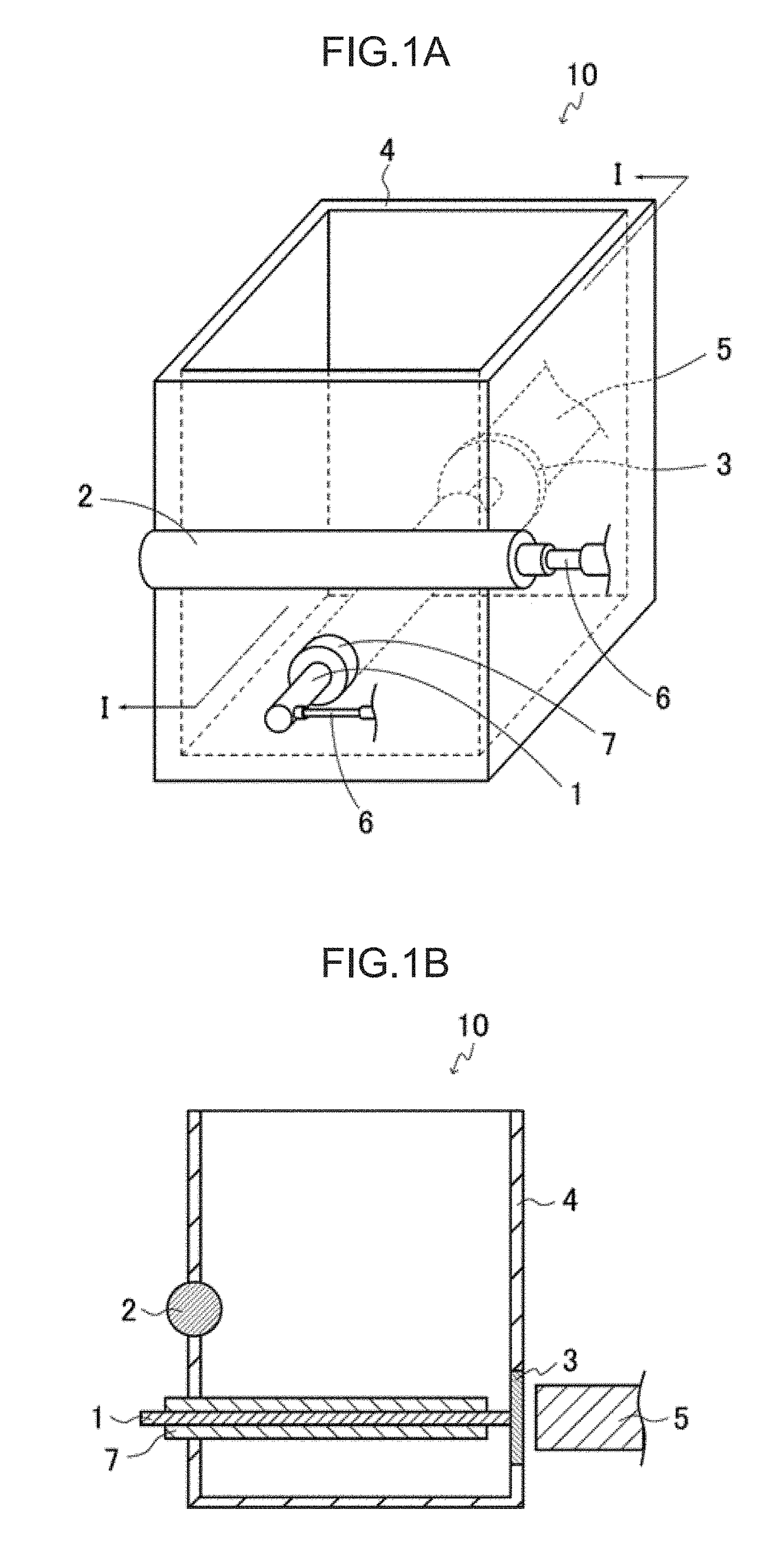
[0089](1) Plasma Spectroscopic Analyzer

[0090]The analyzer according to the above-described embodiment was prepared. Specifically, a bottom-closed columnar container made of transparent PMMA (35 mm (height)×8 mm (width)×6.5 mm (depth)) was prepared. On a side surface of the container 4, a quartz glass was arranged. The electrodes 1 and 2 were arranged in the container 4 and each connected to the constant current section 6 (galvanostat). The electrodes 1 and 2 were arranged horizontally to the bottom surface of the container 4. The electrode 1 was arranged such that one end thereof was in contact with the quartz glass on the side of the container 4. As the electrode 1, a nichrome electrode rod having a diameter of 0.1 mm and a length of 25 mm was used. A portion having 0.5 mm in length...

example 2

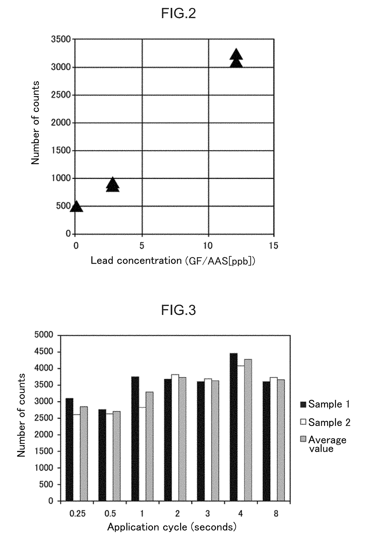
[0105]It was verified that lead contained in urine specimens can be analyzed with only small variations at different application cycles.

[0106]The number of counts (n=2) was measured in the same manner as in the above-described Example 1(2), except that the application cycle of the concentration conditions of Example 1(2) was changed to 0.25, 0.5, 1, 2, 3, 4 or 8 seconds.

[0107]The results thereof are shown in FIG. 3. FIG. 3 is a graph showing the number of counts at different cycles. In FIG. 3, the abscissa axis indicates the application cycle, and the ordinate indicates the number of counts. As shown in FIG. 3, an effect was observed even at the application cycle of 0.25 seconds, and the number of counts increased as the application cycle was extended. Further, higher numbers of counts were obtained at application cycles of 2 seconds or longer. From these results, it was found that, according to the analysis method according to the present disclosure, an analyte can be analyzed over...


PUM


Abstract

A plasma spectroscopic analysis method includes a concentration process including a voltage application period in which voltage is applied to a pair of electrodes in the presence of a sample thereby concentrating an analyte contained in the sample in the vicinity of at least one of the pair of electrodes; and a detection process of generating a plasma by applying voltage to the pair of electrodes and detecting light emitted by the analyte due to the plasma. An electric current between the pair of electrodes is constant while applying voltage for at least a part of the duration of the concentration process.

Description

CROSS-REFERENCE TO RELATED APPLICATIONS[0001]This application claims priority from Japanese Patent Application No, 2016-144930, filed Jul. 22, 2016, and Japanese Patent Application No. 2017-123020, filed Jun. 23, 2017, the disclosures of which are incorporated herein by reference in their entirety.BACKGROUNDTechnical Field[0002]The present disclosure relates to a plasma spectroscopic analysis method and a plasma spectroscopic analyzer.Background Art[0003]As methods of analyzing an analyte contained in a sample, analysis methods utilizing plasma emission are known.[0004]Regarding the analysis methods, Japanese Patent Application Laid-Open (JP-A) No. 2009-128315 discloses a method of analyzing a sample using a radiofrequency plasma mass spectrometer. Further, JP-A No. 2011-180045 and JP-A No. 2012-185064 disclose a method of analyzing a sample by generating a plasma in the sample using a plasma generator including a narrow section and analyzing the plasma emission. Moreover, WO 2006 / 0...

Claims


Application Information

Patent Timeline
IPC IPC(8): G01N21/73G01N33/483G01N33/20
CPCG01N21/73G01N33/483G01N33/20G01N1/40G01N21/67G01N21/69G01N2001/4038G01N33/202
Inventor TAKASU, TSUYOSHI
Owner ARKRAY INC
Why Eureka
Try Eureka