Doherty amplifier and power amplifier
a technology of power amplifier and amplifier, which is applied in the direction of amplifier, amplifier with semiconductor device/discharge tube, amplifier, etc., can solve the problems of large peak to average power ratio (papr), large electrical power consumed by the power amplifier, and large electrical power consumed by the transmitter, so as to prevent the area of an impedance transformer matching circuit from being increased. , the effect of low characteristic impedan
- Summary
- Abstract
- Description
- Claims
- Application Information
AI Technical Summary
Benefits of technology
Problems solved by technology
Method used
Image
Examples
embodiment
[0043]Referring to FIG. 10, a single amplifier according to an embodiment will be described. FIG. 10 is a block diagram of a single amplifier according to an embodiment.
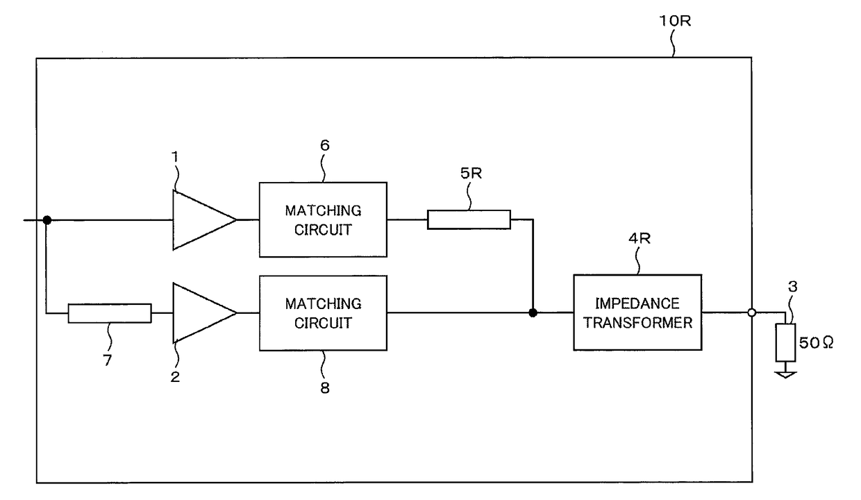
[0044]A single amplifier 30 according to the embodiment is configured of two amplifiers, which are a carrier amplifier 41 and a peak amplifier 42. When the signal level inputted to the single amplifier 30 is low, the peak amplifier 42 is turned to the Off-state, and only the carrier amplifier 41 is operated. When the input signal level of the single amplifier 30 is increased, the peak amplifier 42 is turned on, and both of the carrier amplifier 41 and the peak amplifier 42 are operated. A phase compensation circuit 47 is adjusted so that the outputs of both of the carrier amplifier 41 and the peak amplifier 42 are combined in phase. An impedance transformer 44 converts a load (ZD) 43 of the single amplifier 30, which is smaller than a system load (ZS), into a characteristic impedance, which is smaller than the load 4...
example
[0064]Referring to FIGS. 7 to 9, a power amplifier according to an example of the embodiment will be described. FIG. 7 is a block diagram of the configuration of a power amplifier according to an example. FIG. 8 is a block diagram of the configuration of a single amplifier according to the example. FIG. 9 is an outside diagram of the configuration of a balun circuit according to the example. FIG. 9(A) is the pattern of the front surface, and FIG. 9(B) is the pattern of the back surface.
[0065]In a power amplifier 100A according to the example, a power distribution circuit 32A on the input side and a power combining circuit 33A on the output side are configured of balun circuits. The power distribution circuit 32A is designed to have an input / output impedance of 50 ohms. The power combining circuit 33A is designed to have an input impedance of 12.5 ohms and an output impedance of 50 ohms. The power amplifier 100A is used in a 50-ohm system (e.g. a transmitter).
[0066]A single amplifier...
PUM
 Abstract
Description
Claims
Application Information
 - R&D
- Intellectual Property
- Life Sciences
- Materials
- Tech Scout
- Unparalleled Data Quality
- Higher Quality Content
- 60% Fewer Hallucinations
Browse by: Latest US Patents, China's latest patents, Technical Efficacy Thesaurus, Application Domain, Technology Topic, Popular Technical Reports.
© 2025 PatSnap. All rights reserved.Legal|Privacy policy|Modern Slavery Act Transparency Statement|Sitemap|About US| Contact US: help@patsnap.com


