
Catalytic composite and improved process for dehydrogenation of hydrocarbons

a composite and hydrocarbon technology, applied in the field of catalytic composites, can solve the problems of low desired product selectivity and quality, high exothermicity, and non-oxidative processes

Inactive Publication Date: 2018-02-01
SABIC GLOBAL TECH BV
View PDF6 Cites 1 Cited by
  • Summary
  • Abstract
  • Description
  • Claims
  • Application Information

AI Technical Summary

Benefits of technology

This patent describes a catalyst composition and methods for its use in a process for producing olefins from alkanes through a process of adiabatic, non-oxidative dehydrogenation. The catalyst composition includes a dehydrogenation catalyst, a semimetal, and a carrier, which helps support the catalyst. The sememetal is inert towards the dehydrogenation process and releases heat in response to a reducing or oxidizing stage of the process. The patent also describes a fixed bed reactor and a process for regenerating the catalyst by reducing, purging, and oxidizing it. The technical effects of this patent include improved yields of olefins through a more efficient and selective process using a specific catalyst composition.

Problems solved by technology

Disadvantages associated with oxidative dehydrogenation include high exothermicity and low desired product selectivity and quality.
Non-oxidative processes (i.e., direct dehydrogenation or catalytic dehydrogenation), on the other hand, are endothermic and can suffer from the requirement of a continuous heat supply to initiate the endothermic reaction.
These high temperatures can also lead to thermal cracking of the alkanes, which can lead to undesirable non-selective side reactions that result in formation of byproducts.
However, since the duration of the regeneration cycle is short, there is a strong likelihood for the formation of a vertical temperature gradient and pressure drop across the catalyst bed, which adversely affects the overall yield of the olefin product.
Hence, with hot air flow and combustion of coke as the sole heat sources, heat input to the catalyst bed remains a critical limiting factor to Catofin dehydrogenation processes.

Method used

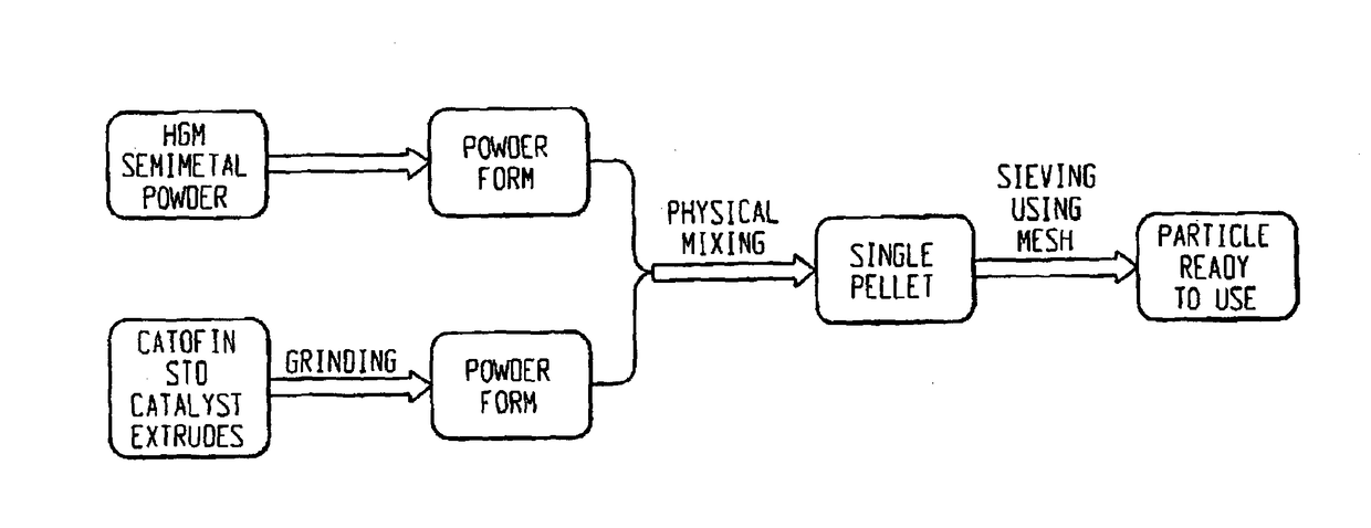
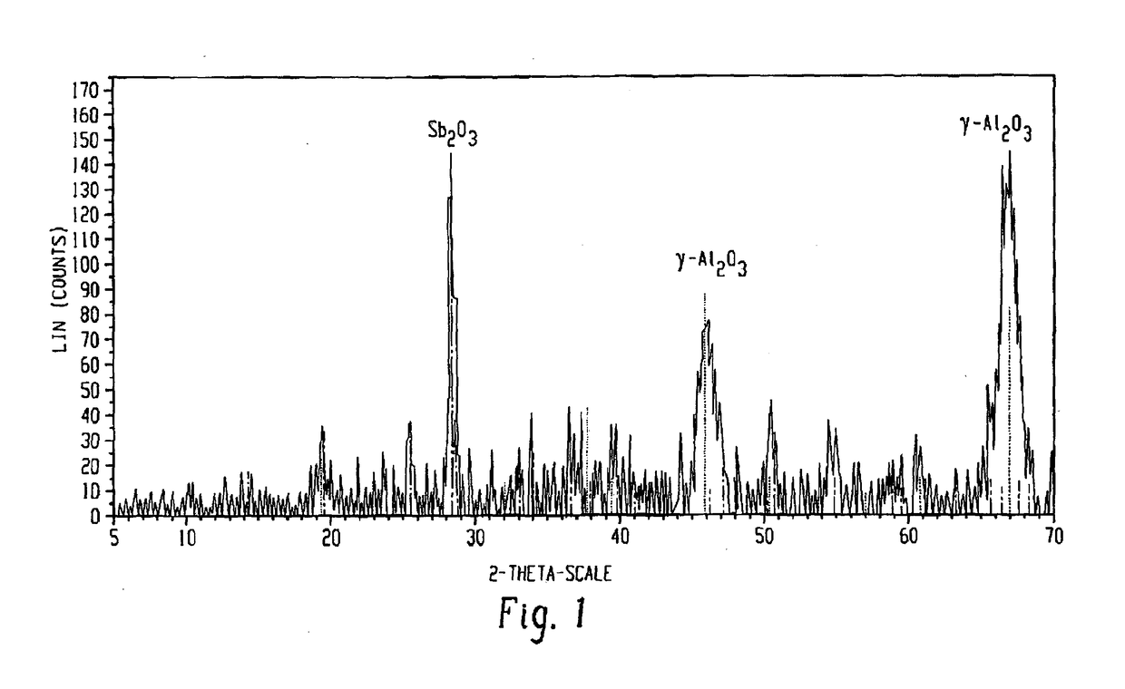
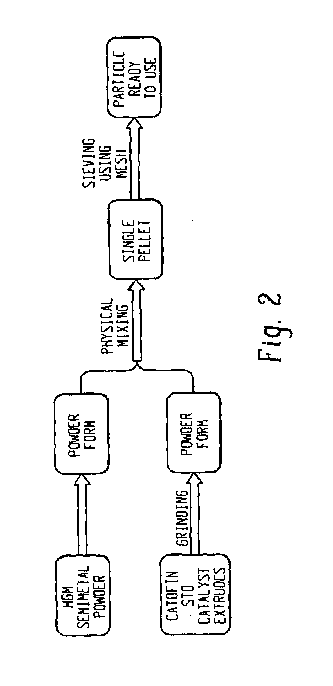

Image

  • Catalytic composite and improved process for dehydrogenation of hydrocarbons
  • Catalytic composite and improved process for dehydrogenation of hydrocarbons
  • Catalytic composite and improved process for dehydrogenation of hydrocarbons

Examples


embodiment 1

[0058] A catalytic composite suitable for a cyclic process of adiabatic, non-oxidative dehydrogenation of an alkane into an olefin, comprising: a dehydrogenation catalyst; a semimetal; and a carrier supporting the dehydrogenation catalyst and the semimetal; wherein the semimetal is inert towards the dehydrogenation, and releases heat in situ when exposed to at least one of a reducing stage and an oxidizing stage of the cyclic process.

[0059]Embodiment 2: The catalytic composite of Embodiment 1, wherein the semimetal is at least one of boron, silicon, germanium, arsenic, antimony, tellurium, polonium, and astatine.

embodiment 3

[0060] The catalytic composite of any of the previous Embodiments, wherein the semimetal is a combination comprising at least one of boron, silicon, germanium, arsenic, antimony, tellurium, polonium, and astatine.

embodiment 4

[0061] The catalytic composite of any of the previous Embodiments, wherein the semimetal is antimony.


PUM

PropertyMeasurementUnit
Particle sizeaaaaaaaaaa
Energyaaaaaaaaaa

Abstract

A catalytic composite for a cyclic process of adiabatic, non-oxidative dehydrogenation of an alkane into an olefin, comprising a dehydrogenation catalyst, a semimetal and a carrier supporting the catalyst and the semimetal. During the reduction and / or regeneration stages of the adiabatic process, the semimetal releases heat which can be used to initiate the dehydrogenation reactions, which are endothermic in nature, thereby reducing the need for hot air flow and combustion of coke as heat input. The semi-metal is inert towards the dehydrogenation reaction itself, alkane feed and olefin product as well as other side reactions of the cyclic process such as cracking and decoking.

Description

BACKGROUND OF THE INVENTIONTechnical Field[0001]The present disclosure relates to catalytic composites for dehydrogenation processes. More specifically, the present disclosure relates to catalytic composites incorporating at least one catalytically inactive semimetal and adiabatic, non-oxidative, cyclic dehydrogenation processes wherein these catalytic composites are used.Description of the Related Art[0002]The “background” description provided herein is for the purpose of generally presenting the context of the disclosure. Work of the presently named inventors, to the extent it is described in this background section, as well as aspects of the description which may not otherwise qualify as prior art at the time of filing, are neither expressly or impliedly admitted as prior art against the present invention.[0003]The dehydrogenation of hydrocarbons, involves the breaking of two carbon-hydrogen (C—H) bonds with the simultaneous formation of a hydrogen molecule (H2) and a molecule co...

Claims


Application Information

Patent Timeline
IPC IPC(8): B01J23/652C07C5/32B01J21/04B01J8/02B01J23/18B01J35/02
CPCB01J23/6522B01J23/18B01J35/026B01J21/04B01J8/02C07C5/325B01J2208/027C07C2523/652C07C2523/644B01J23/26B01J23/622B01J23/644B01J23/6445B01J23/843B01J23/8435B01J27/0576C07C5/324B01J35/30B01J38/06B01J38/12Y02P20/584C07C11/02B01J35/50
Inventor MONDAL, KARTICK CHANDRACHOWDHURY, DIPABALI ROYSARAVANAN, VELAYUTHAM
Owner SABIC GLOBAL TECH BV
Learn More