Electro-optic modulator, microwave photonic link including an electro-optic modulator, and method of communicating a signal with an electro-optic modulator

a microwave photonic link and modulator technology, applied in the field of electrooptic modulators, can solve the problems of limited success in achieving a highly linear modulator for microwave photonic links, nonlinear distortions, and nonlinear distortions, and achieve high spur-free dynamic range, enhance linearity of single ring resonator design, and wide bandwidth

Inactive Publication Date: 2018-02-01
MICHIGAN TECHNOLOGICAL UNIVERSITY
View PDF8 Cites 15 Cited by
  • Summary
  • Abstract
  • Description
  • Claims
  • Application Information

AI Technical Summary

Benefits of technology

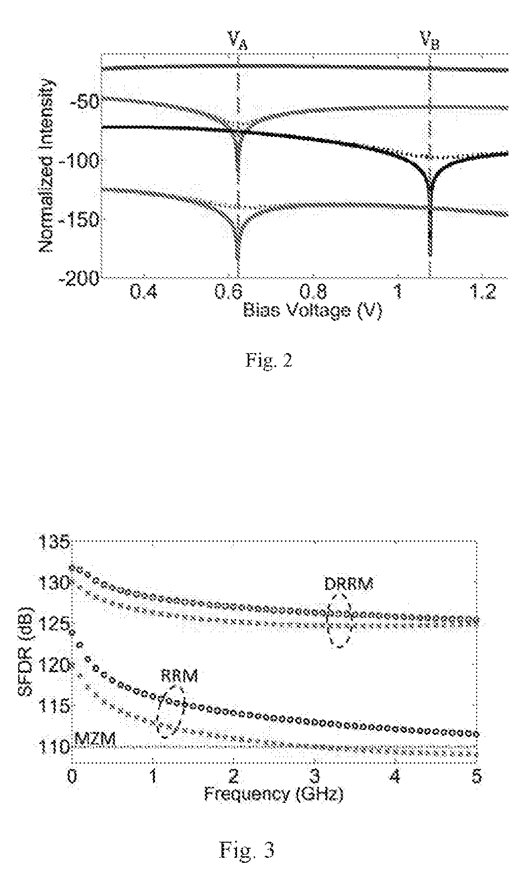
[0003]In one embodiment, the invention provides a highly linear dual ring resonator modulator design. The dual ring resonator modulator provides high spur-free dynamic range in a wide bandwidth. Harmonic and intermodulation distortions are theoretically analyzed in a single ring resonator modulator structure and a strategy is proposed to enhance the linearity of the single ring resonator design for wide bandwidth applications by utilizing dual ring resonator modulators. Third order intermodulation distortion is suppressed with proper splitting ratio of optical and radio frequency power and optimum direct current biasing of the ring resonators. The structure shows the ability to obtain spur-free dynamic range more than 130 decibels at 1 hertz microwave operating frequency while keeping the spur-free dynamic range greater than 125 decibels and up to 5 gigahertz bandwidth.
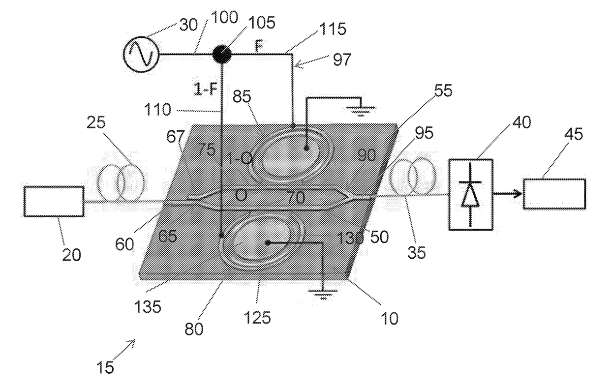
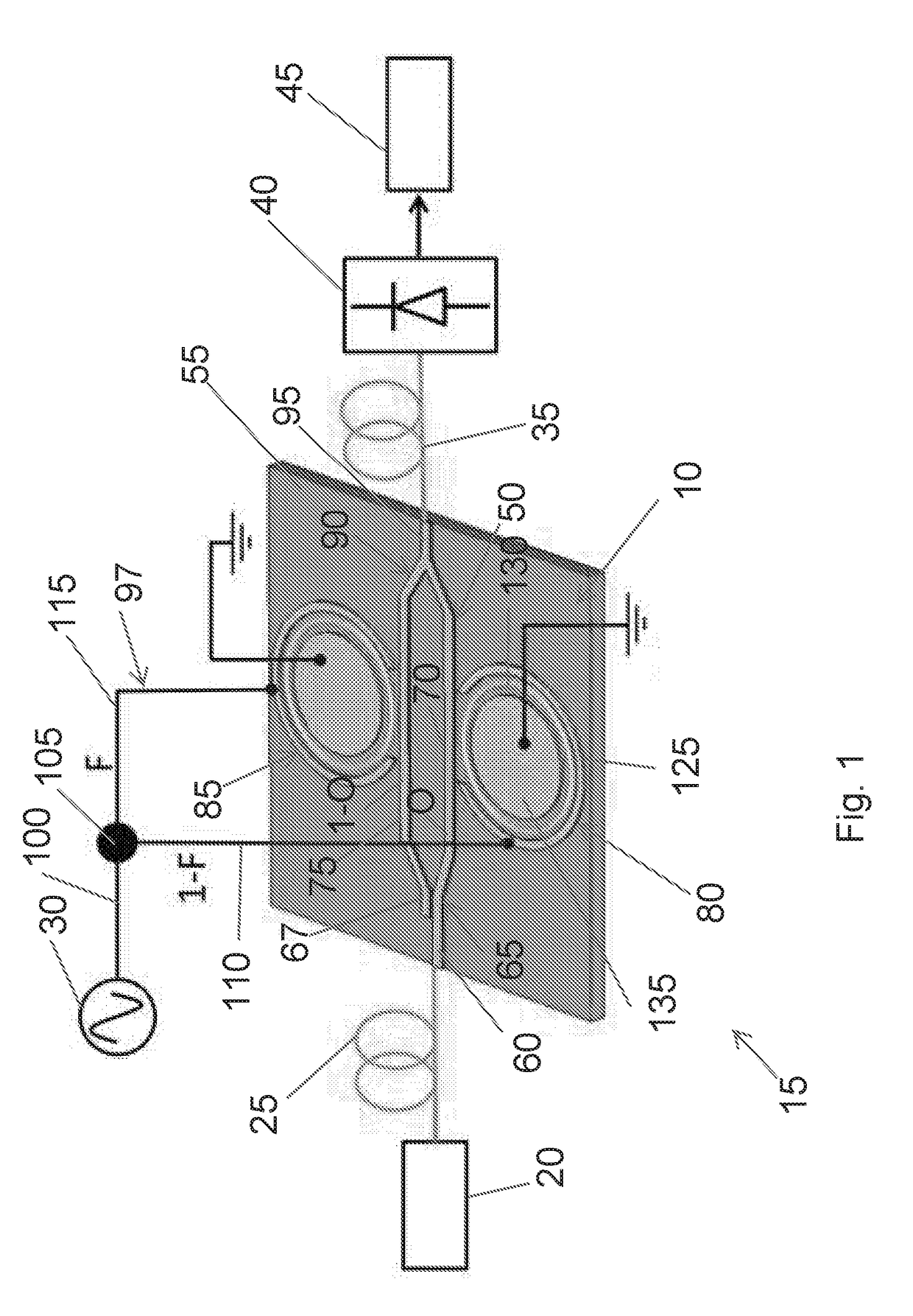
[0004]In another embodiment, the invention provides an electro-optic modulator for coupling to an optical source providing an optical power and a radio frequency source providing a radio frequency power. The electro-optic modulator includes a waveguide to receive the optical power, a first ring resonator modulator, and a second ring resonator modulator. The first ring resonator modulator and the second ring resonator modulator receive the radio frequency power, and are coupled to the waveguide for modulating the optical power with the radio frequency power, thereby providing a resultant power. Combination of the first ring resonator modulator and the second ring resonator modulator, substantially suppress third order intermodulation distortion of the resultant power.
[0006]In a further embodiment, the invention provides a method of communicating a signal with an electro-optic modulator. The method includes receiving an optical power providing a carrier signal, receiving a first radio frequency power providing a communication signal, and receiving a second radio frequency power providing the communication signal. The method further includes splitting the optical power into a first optical power and a second optical power, transmitting the first optical power over a first waveguide segment of the waveguide to a first ring resonator modulator, and transmitting the second optical power over a second waveguide segment of the waveguide to a second ring resonator modulator. The method also includes providing the first radio frequency power to the first ring resonator modulator, providing the second radio frequency power to the second ring resonator modulator, modulating the first optical power with the first radio frequency power using the first ring resonator modulator, and modulating the second optical power with the second radio frequency power using the second ring resonator modulator. Combination of the first ring resonator modulator and the second ring resonator modulator, substantially suppress third order intermodulation distortion of the resultant power.

Problems solved by technology

Nonlinear distortions remain as one of the fundamental limitations for full scale implementation of microwave photonic links.
Current microwave photonic links may utilize Mach-Zehnder interferometers (MZI) as electro-optic (E / O) modulators, resulting in nonlinear distortions.
Ongoing research efforts have been focused on achieving a highly linear modulator for microwave photonic links with limited success.
While gains have been made, the devices are very complex.
The exact value of the coupling coefficient is highly dependent upon the fabrication process and design layout making it difficult to predict this value to great precision.
The resonator-assisted Mach-Zehnder interferometer and interferometric modulator with phase-modulating and cavity-modulating component structures add complexity to the fabrication and integration process and their operation is sensitive to the structure properties including loss factor of the ring, coupling coefficient, and working frequency.
However, the bandwidth of ring resonator modulators is limited because of the resonance characteristics similar to other resonance type of modulators.
In all of the resonator type modulators, including resonator-assisted Mach-Zehnder interferometer and interferometric modulator with phase-modulating and cavity-modulating components, bandwidth is a limiting factor in dynamic ranges.
Obtained equations show the influence of the bandwidth in suppressing the spur-free dynamic range making single ring resonator modulators not suitable for the wide bandwidth applications.
However, by increasing the radio frequency operating frequency from 1 hertz to 500 megahertz the suppressing of the harmonics at VA and VB is diminished considerably resulting in spur-free dynamic range reduction.
However, the cancellation process of the third harmonic power will also slightly suppress the fundamental signal.
However, by working at higher frequencies, fifth harmonic contribution in third order intermodulation distortion power increases reducing spur-free dynamic range.

Method used


Image

  • Electro-optic modulator, microwave photonic link including an electro-optic modulator, and method of communicating a signal with an electro-optic modulator
  • Electro-optic modulator, microwave photonic link including an electro-optic modulator, and method of communicating a signal with an electro-optic modulator
  • Electro-optic modulator, microwave photonic link including an electro-optic modulator, and method of communicating a signal with an electro-optic modulator

Examples


Embodiment Construction

[0015]Before any embodiments of the invention are explained in detail, it is to be understood that the invention is not limited in its application to the details of construction and the arrangement of components set forth in the following description or illustrated in the following drawings. The invention is capable of other constructions and of being practiced or of being carried out in various ways.

INTRODUCTION

[0016]Microwave photonic links (MPLs) are critical for applications such as wireless-access networks, antenna remoting, and video distribution networks. See, for example, “Wireless future drives microwave photonics,”Nat Photon, vol. 5, pp. 724-724, 12 / / print 2011, M. L. VanBlaricum, “Photonic systems for antenna applications,”Antennas and Propagation Magazine, IEEE, vol. 36, pp. 30-38, 1994, and M. Nazarathy, J. Berger, A. J. Ley, I. M. Levi, and Y. Kagan, “Progress in externally modulated AM CATV transmission systems,”Lightwave Technology, Journal of, vol. 11, pp. 82-105, 1...


PUM

PropertyMeasurementUnit
frequenciesaaaaaaaaaa
radio frequency operating frequencyaaaaaaaaaa

Abstract

An electro-optic modulator coupled to an optical source providing an optical power and a radio frequency source providing a radio frequency power. The electro-optic modulator includes a waveguide to receive the optical power, a first ring resonator modulator, and a second ring resonator modulator. The first ring resonator modulator and the second ring resonator modulator receives the radio frequency power, and are coupled to the waveguide for modulating the optical power with the radio frequency power. The first ring resonator modulator and the second ring resonator modulator, with the waveguide, substantially suppress third order intermodulation distortion of a combined power. Also disclosed are a microwave photonic link having the electro-optic modulator and a method of communicating a signal with the electro-optic modulator.

Description

RELATED APPLICATIONS[0001]This application claims the benefit of U.S. Patent Application No. 62 / 115,556, filed on Feb. 12, 2015, the content of which is incorporated herein by reference.BACKGROUND[0002]The invention relates to an electro-optic modulator, a microwave photonic link including an electro-optic modulator, and a method of communicating a signal with an electo-optic modulator.SUMMARY[0003]In one embodiment, the invention provides a highly linear dual ring resonator modulator design. The dual ring resonator modulator provides high spur-free dynamic range in a wide bandwidth. Harmonic and intermodulation distortions are theoretically analyzed in a single ring resonator modulator structure and a strategy is proposed to enhance the linearity of the single ring resonator design for wide bandwidth applications by utilizing dual ring resonator modulators. Third order intermodulation distortion is suppressed with proper splitting ratio of optical and radio frequency power and opti...

Claims


Application Information

Patent Timeline
Patent Type & Authority Applications(United States)
IPC IPC(8): G02F1/225H04B10/50G02B6/293
CPCG02F1/2257G02B6/29338H04B10/505G02F2203/15G02F2001/212G02F1/2255G02F1/212
Inventor MIDDLEBROOK, CHRISTOPHER T.HOSSEINZADEH, ARASH
Owner MICHIGAN TECHNOLOGICAL UNIVERSITY
Why Eureka
Try Eureka