Particle counter

a technology of particle counter and counter, which is applied in the field of particle counter, can solve the problems of difficult to count small-sized particles, large background noise in the measurement of particles in chemical solutions,

Active Publication Date: 2018-02-08
RION COMPANY
View PDF1 Cites 12 Cited by
  • Summary
  • Abstract
  • Description
  • Claims
  • Application Information

AI Technical Summary

Benefits of technology

[0012]With this invention, a particle counter that can count particles with a small particle size at a satisfactory S / N ratio can be obtained.

Problems solved by technology

Thus, measuring particles in the chemical solution involves larger background noise than that in the case of measuring the particles in the water.
This makes it difficult to count small-size particles (for example, 30 nm or less).

Method used


Image

  • Particle counter
  • Particle counter
  • Particle counter

Examples


first embodiment

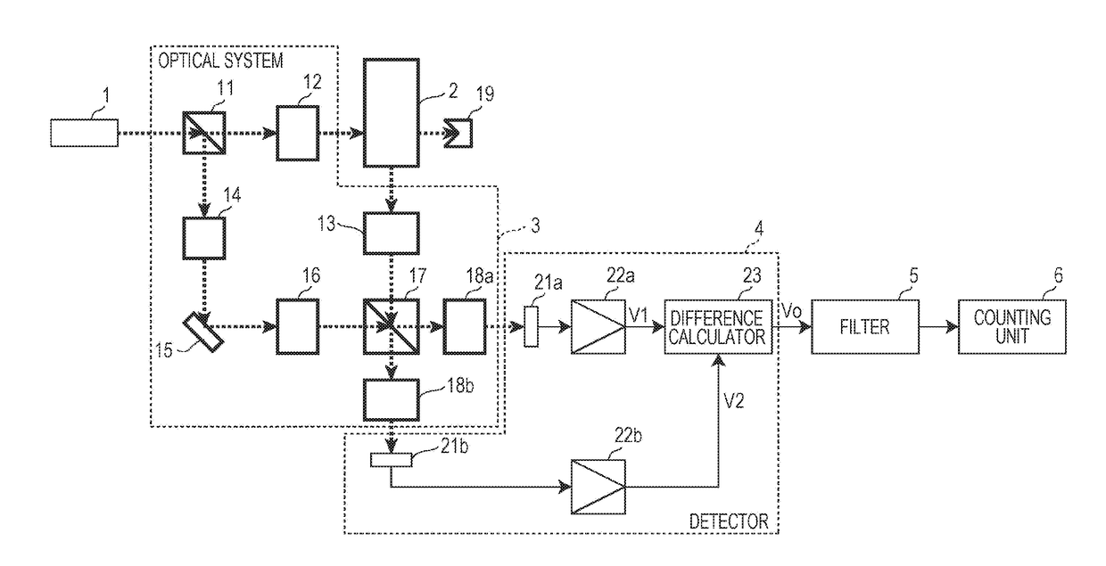
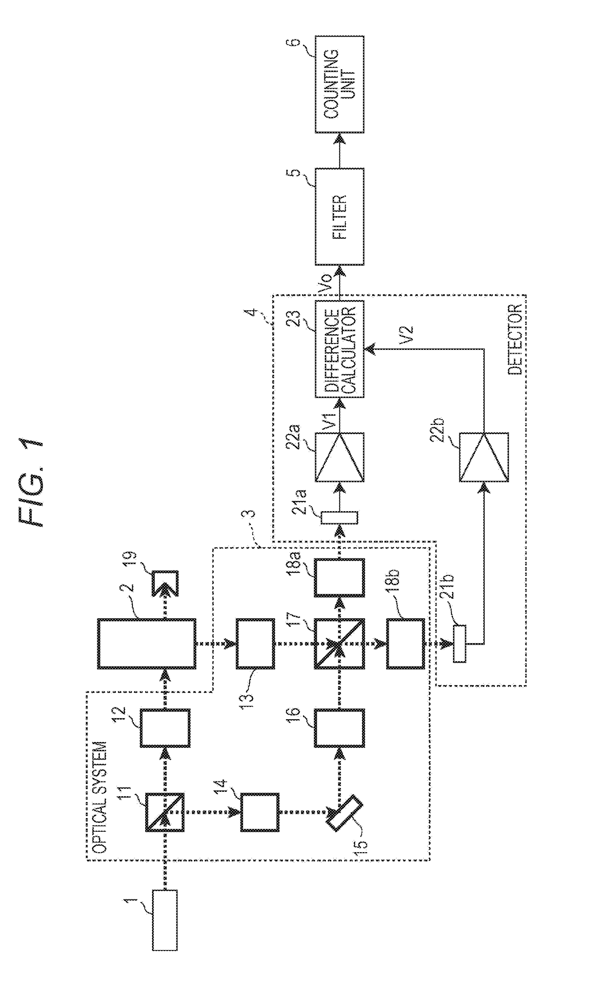
[0019]FIG. 1 is a block diagram illustrating a structure of a particle counter according to the first embodiment of this invention. The particle counter illustrated in FIG. 1 has a light source 1, a flow cell 2, an optical system 3, a detection circuit 4, a filter 5, and a counting unit 6.

[0020]The light source 1 is a light source emitting light (laser light here) at a stable frequency. In the embodiment, the light source 1 emits a high-coherence single-mode light. For example, as the light source 1, a laser light source with a wavelength of 532 nm and an output of about 500 mW is used.

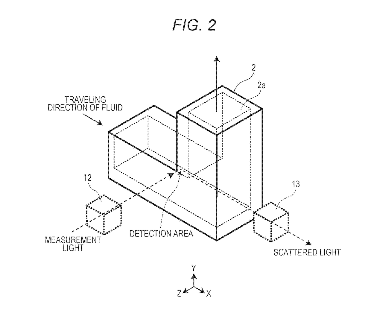
[0021]The flow cell 2 forms a flow passage for a fluid containing particles to be counted. In the embodiment, the fluid containing particles to be counted is a liquid.

[0022]FIG. 2 is a perspective view of an example of the flow cell 2 illustrated in FIG. 1. As illustrated in FIG. 2, the flow cell 2 is bent in an L shape. The flow cell 2 is a transparent tubular member that forms a bent flow passage 2a...

second embodiment

[0066]In the first embodiment, the first interference light and the second interference light are received as interference lights by the scattered light from the particles and the reference light. The difference between the electrical signals V1 and V2 of both is used as the detection signal Vo. In the second embodiment, instead of this, the electrical signal from either the first interference light or the second interference light is used as the detection signal Vo. In this case, the detection signal Vo also contains an AC component resulting from the interference light by the scattered light from the particles and the reference light. Accordingly, the particles can be counted in the same manner. In this case, one light receiving element may be provided.

[0067]Other components of a particle counter according to the second embodiment are the same as those of the first embodiment, and descriptions thereof will be omitted.

[0068]The foregoing respective embodiments are preferred example...


PUM

PropertyMeasurementUnit
sizeaaaaaaaaaa
particle sizeaaaaaaaaaa
wavelengthaaaaaaaaaa

Abstract

An irradiation optical system 12 irradiates a fluid flowing in a flow passage 2a with one light among a plurality of lights obtained by branching light from a light source 1 and forms the detection area. A detection optical system 13 makes scattered light with a different direction from an optical axis of the irradiation optical system enter a beam splitter 17 among the scattered lights from particles contained in the fluid in this detection area. Meanwhile, a beam expander 16 makes another light among the plurality of lights enter the beam splitter 17 as reference light. A detector 4 receives an interference light, by the scattered light and the reference light, obtained by the beam splitter 17 by light receiving elements and generates a detection signal corresponding to the interference light. A counting unit 6 counts the particles based on this detection signal.

Description

TECHNICAL FIELD[0001]This invention relates to a particle counter.BACKGROUND ART[0002]There have been provided particle counters as devices for measuring particles in fluids, which are, for example, liquids such as a chemical solution and water, or gas such as air. At the particle counter, a fluid containing particles is irradiated with a laser beam. Scattered light from the particles in the fluid is observed to count the particles (for example, refer to Patent Literature 1).[0003]For example, in the manufacture of semiconductor wafers, the particles of impure substances contained in the chemical solution to be used exert influence on the manufacturing process. Accordingly, a particle counter is used to count the particles in the chemical solution to control the state of the chemical solution. In the chemical solution, scattered light (background light) and the like are generated by the medium (namely, the chemical solution itself). Thus, measuring particles in the chemical solution...

Claims


Application Information

Patent Timeline
Patent Type & Authority Applications(United States)
IPC IPC(8): G01N15/02G01N15/14G01N21/45G01N15/06
CPCG01N15/0205G01N15/06G01N15/1434G01N21/45G01N2015/1486G01N2015/0011G01N2015/1445G01N15/1459G01N2015/0038G01N2015/0053G01N2015/1454G01N2015/1493G01N15/14
Inventor MATSUDA, TOMONOBUSHIMMURA, MASAKIYAMAKAWA, YUKI
Owner RION COMPANY
Why Eureka
Try Eureka