Applique and method for thermographic inspection

Active Publication Date: 2018-02-15
THE BOEING CO
View PDF43 Cites 4 Cited by
  • Summary
  • Abstract
  • Description
  • Claims
  • Application Information

AI Technical Summary

Benefits of technology

[0011]By utilizing an applique, such as a removable or reusable applique, in place of spray or brush coatings for thermography inspection, surface preparation and cleaning time may be reduced. By reducing surface preparation and cleaning time, inspection times may are shortened and cost savings may be achieved. By including a plurality of surface features (e.g., cavities, microstructures, nanoparticles, etc.) in the applique, the ap

Problems solved by technology

A common defect to inspect for in such structures is a disbond, or separation of the aluminum honeycomb core from one of the two face sheets.
Because thermography inspection often utilizes flashlamps to inject a heat generating energy pulse into the component, bare metal or very light colored surfaces of the component may reject incident energy and distort thermographic emitted infrared readings.
Reflection of the light from a flashlamp may reduce the usefulness of a thermographic image of the component used to identify a location of a defect of the component.
However, coatings may be applied non-uniformly, causing variations in heat transfer into the part and infrared emission from the part.
A thermographic inspection may begin after the flat black paint has dried, which increases an amount of time associated with preparing for and performing the thermographic inspection.
Additionally, the flat black paint coating is prone to scratches that may

Method used


Image

  • Applique and method for thermographic inspection
  • Applique and method for thermographic inspection
  • Applique and method for thermographic inspection

Examples


Example

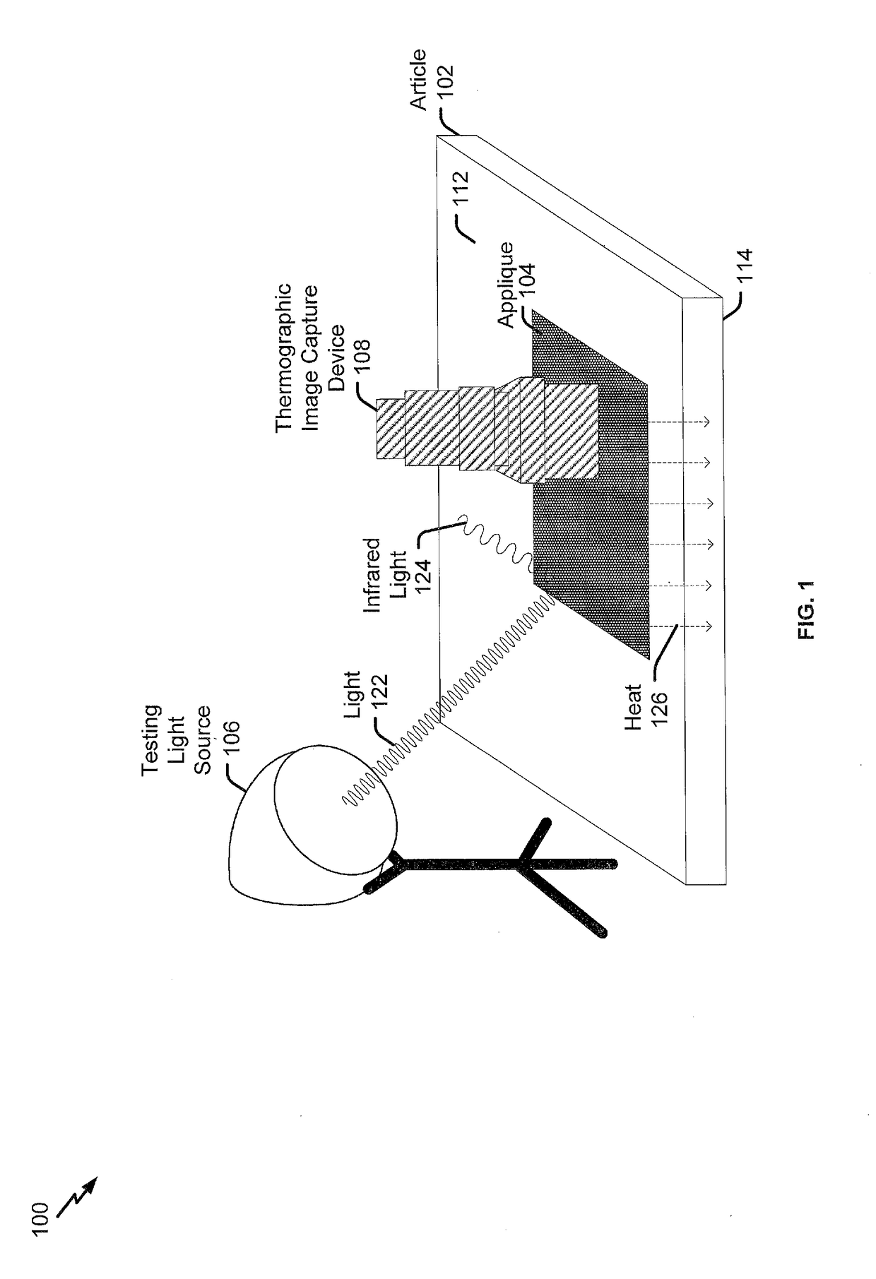
[0023]Implementations disclosed herein enable non-destructive inspection of articles, such as components of an aircraft. In particular, an applique may be affixed to an article and a thermographic inspection may be performed to examine the article for structural and sub-surface defects. In some implementations, the applique may be removable and reusable. Thermography involves capturing infrared light indicative of a heat distribution of an object. Thermographic inspection involves evaluating the heat distribution (e.g., temperature differences between areas of the object) to indicate structural or sub-surface defects in the article. To illustrate, a structural or sub-surface defect may impair heat transfer (e.g., conduction of thermal energy) between a surface and the structure of an article. As another example, a structural or sub-surface defect may impair conduction of thermal energy between a first surface and a second surface of an article.

[0024]When heat is applied to the surfa...


PUM


Abstract

A method of thermographic inspection includes absorbing, at an applique applied to a test area of an article, light from a testing light source. The method further includes emitting, by the applique, thermal radiation directed to a capture device, the thermal radiation corresponding to at least a portion of the light absorbed by the applique.

Description

GOVERNMENT LICENSE RIGHTS[0001]This invention was made with Government support under FA8650-10-D-5210-024 awarded by Air Force Research Laboratory. The Government has certain rights in this invention.FIELD OF THE DISCLOSURE[0002]The present disclosure is generally related to appliques and methods for thermographic inspection.BACKGROUND[0003]Thermography inspection, such as infrared thermography inspection, is a nondestructive inspection method that is commonly utilized in field inspection of structures, such as aircraft structures. Thermography inspection utilizes the transfer of energy into an object of inspection to generate heat and detects heat energy (e.g., infrared light) that is dissipated from the object. In a particular example, thermography (e.g., infrared thermography) is used to inspect wing and stabilizer components that are fabricated from aluminum honeycomb which may be adhesively bonded between two aluminum or composite face sheets of varying thicknesses. A common de...

Claims


Application Information

Patent Timeline
IPC IPC(8): G01J5/00G01J5/10G01N21/88
CPCG01J5/0066G01J5/0003G01J5/10G01N21/8806G01J5/0887G01J5/0896G01J2005/0077G01N25/72
Inventor ENGELBART, ROGER W.SMITH, NATHAN R.SHAWGO, LOYAL B.
Owner THE BOEING CO
Why Eureka
Try Eureka