
Method for operating a combustion system

Inactive Publication Date: 2018-03-01
SIEMENS AG
View PDF4 Cites 1 Cited by
  • Summary
  • Abstract
  • Description
  • Claims
  • Application Information

AI Technical Summary

Benefits of technology

The invention provides a new method for controlling the pilot flame in low oxygen content air combustion for gas turbine engines. By controlling the feed of oxygen and fuel to the combustion system, the method allows for stable operation of the pilot flame while reducing the amount of oxygen needed and lowering costs. This method also ensures reliable and effective performance of the combustion system and gas turbine engine.

Problems solved by technology

One is to operate the main flame at a high temperature, like above 1200° C. Disadvantageously, this generates high and harmful amounts of combustion by-products.
However, such lean flames can be very unstable and only small changes in the equivalence ration can cause a disadvantage and troublesome flame out.
According to the high temperature of the pilot burner flame the overall performance of the combustion system, like temperature or waste emission, is affected negatively.
Consequently, the performance of the combustion system and hence the gas turbine engine is unstable and unreliable.

Method used


Image

  • Method for operating a combustion system
  • Method for operating a combustion system
  • Method for operating a combustion system

Examples


Embodiment Construction

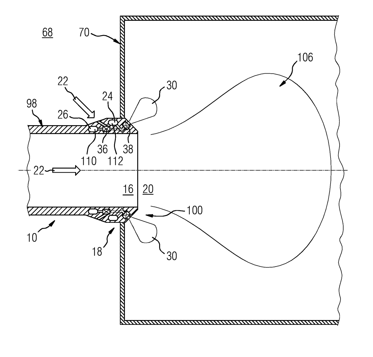
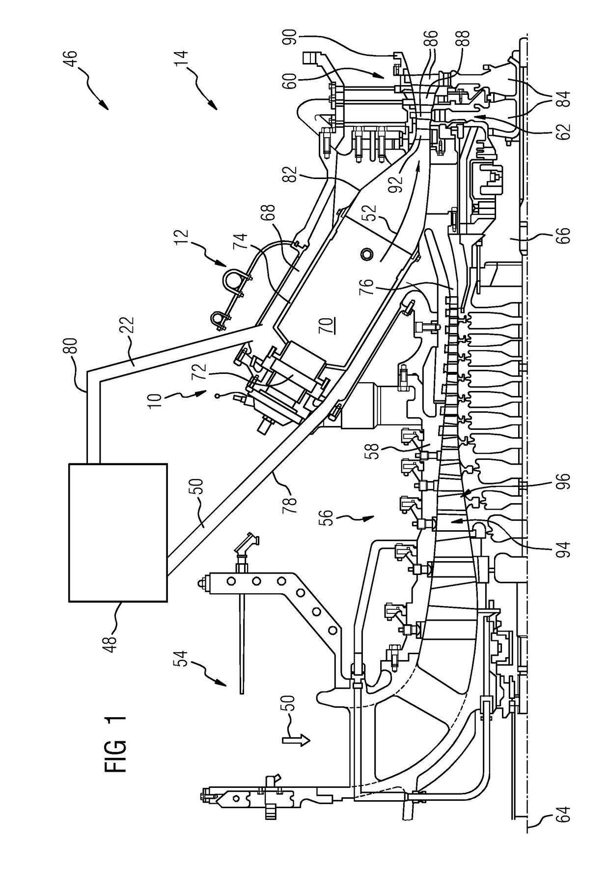
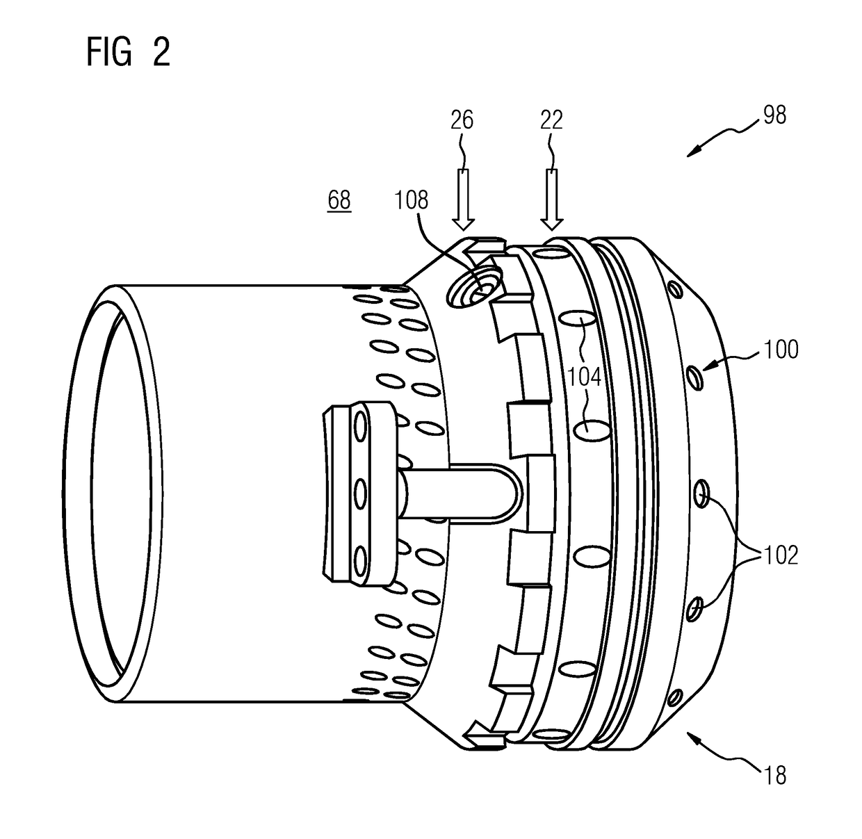
[0046]The terms upstream and downstream refer to the flow direction of the airflow and / or working gas flow through the gas turbine engine 14 unless otherwise stated. If used and not otherwise specified, the terms axial, radial and circumferential are made with reference to a rotational axis 64 of the gas turbine engine 14.

[0047]FIG. 1 shows an example of a gas turbine engine unit 46 with a gas turbine engine 14 and a unit 48 for an oxygen extraction process in a sectional view. The gas turbine engine 14 comprises, in flow series of a working fluid, like air 22, 50 or a combustion gas 52, an air inlet 54 and a compressor section 56 with a compressor 58, a combustion section 12 with a combustion system 10 and a turbine section 60 with a turbine 62, which are generally arranged in flow series in the direction of a longitudinal or rotational axis 64. The gas turbine engine 14 further comprises a shaft 66 which is rotatable about the rotational axis 64 and which extends longitudinally th...


PUM


Abstract

A method for operating a combustion system of a combustion section of a gas turbine engine having at least one main burner arrangement and at least one pilot burner arrangement, wherein the at least one main burner arrangement and the at least one pilot burner arrangement are operated with an air-fuel mixture. The method includes: operating the at least one main burner arrangement with O2-lean air, enriching an air of the air-fuel mixture of the at least one pilot burner arrangement and / or a fuel of the air-fuel mixture of the at least one pilot burner arrangement and / or the air-fuel mixture of the at least one pilot burner arrangement with oxygen and preferably with pure oxygen.

Description

CROSS REFERENCE TO RELATED APPLICATIONS[0001]This application is the US National Stage of International Application No. PCT / EP2016 / 051904 filed Jan. 29, 2016, and claims the benefit thereof. The International Application claims the benefit of European Application No. EP15155956 filed Feb. 20, 2015. All of the applications are incorporated by reference herein in their entirety.FIELD OF THE INVENTION[0002]The present invention relates to a method for operating a combustion system of a combustion section of a gas turbine engine comprising at least one main burner arrangement and at least one pilot burner arrangement, wherein the at least one main burner arrangement and the at least one pilot burner arrangement are operated with an air-fuel mixture. The present invention further relates to a combustion system as well as to a combustion system embodied to perform the inventive method and to a gas turbine engine with such a combustion system.BACKGROUND TO THE INVENTION[0003]In a gas turbi...

Claims


Application Information

Patent Timeline
IPC IPC(8): F23R3/34F23R3/20F23R3/28F23D14/32
CPCF23R3/343F23R3/20F23R3/286F23D14/32F23R2900/03343F23D2900/00014Y02E20/34
Inventor OFVERSTEDT, TOMAS
Owner SIEMENS AG
Learn More