Pulse wave detection device and pulse wave detection program

a detection device and pulse wave technology, applied in the direction of instruments, catheters, image enhancement, etc., can solve the problems of difficult use in a practical scene such as the detection of the pulse wave of a driver by mounting a pulse wave detection device on a vehicle, and the detection accuracy is reduced, so as to improve the accuracy of pulse wave detection, photograph easily, and extract the

Active Publication Date: 2018-03-08
EQUOS RES
View PDF1 Cites 8 Cited by
  • Summary
  • Abstract
  • Description
  • Claims
  • Application Information

AI Technical Summary

Benefits of technology

[0034](1) According to the invention described in claim 1, accuracy of pulse wave detection can be improved since a disturbance element shown on a moving image is excluded and only a skin portion is taken out, a pulse wave can be detected therefrom.
[0035](2) According to the invention described in claim 2, the pulse wave can be detected from the face which can be photographed easily since the skin is usually exposed.
[0036](3) According to the invention described in claim 3, the skin portion can be easily extracted by comparison with a reference component.
[0037](4) According to the invention described in claim 4, by employing a combination of color space components suitable for an observation target (since a target observed by light is different between the skin and the pulse wave), robustness against the disturbance element can be improved.
[0038](5) According to the invention described in claim 5, by combining an H component found to be suitable in specification of the skin portion and a Q component found to be suitable for pulse wave detection, robustness against the disturbance element can be improved.
[0039](6) According to the invention described in claim 6, by including color space conversion processing not in an external device but inside a pulse wave detection device, processing speed is improved, and the pulse wave can be detected from the moving image easily on a real time basis.

Problems solved by technology

However, this technology is performed under an ideal environment of a laboratory, and there has been a problem that use in a practical scene such as detection of the pulse wave of a driver by mounting a pulse wave detection device on a vehicle is difficult due to various disturbance elements.
Moreover, since a background 102 outside the face and a region where the pulse wave cannot be detected such as hair, eyes, eyebrows, mouth and the like are also included in the evaluation region 101, there is also a problem that detection accuracy lowers.

Method used


Image

  • Pulse wave detection device and pulse wave detection program
  • Pulse wave detection device and pulse wave detection program
  • Pulse wave detection device and pulse wave detection program

Examples


first embodiment

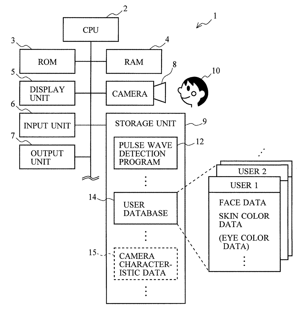
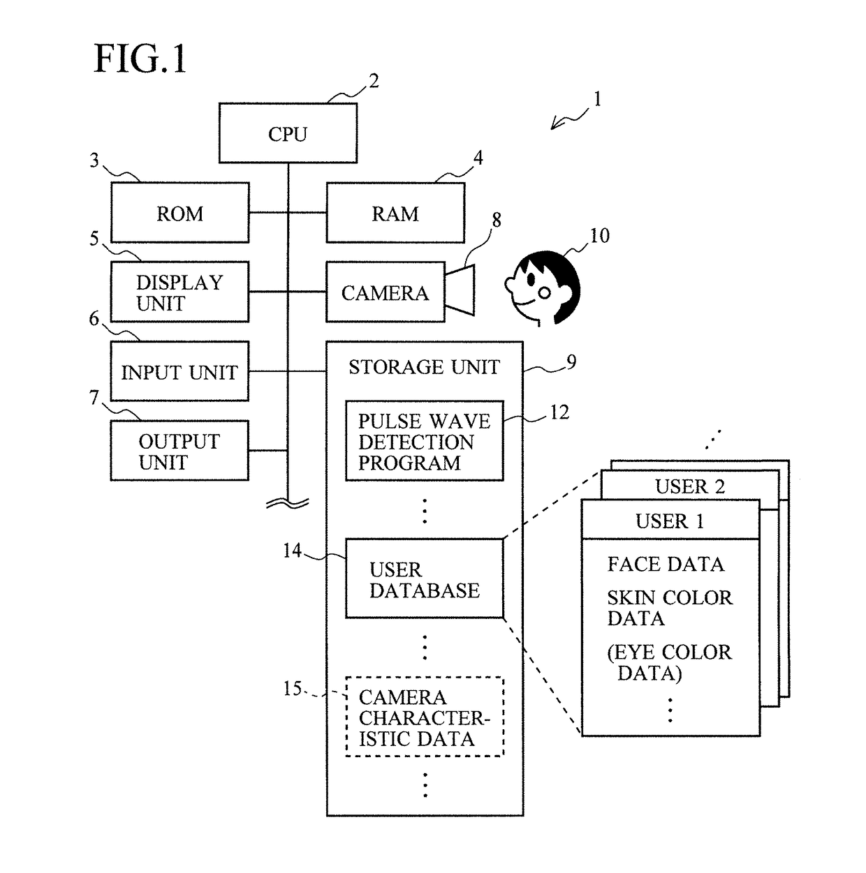
[0085]FIG. 1 is a view illustrating configuration of the pulse wave detection device 1 according to this embodiment.

[0086]The pulse wave detection device 1 is mounted on a vehicle, for example, and monitors a pulse wave of a passenger (a driver or a passenger on a seat next to the driver's) and grasps physiological states such as a physical condition or a tensed state of the driver.

[0087]Moreover, the device can be used for detecting / monitoring a pulse wave of a patient or a victim at a medical site or a disaster site.

[0088]The pulse wave detection device 1 includes a CPU (Central Processing Unit) 2, a ROM (Read Only Memory) 3, a RAM (Random Access Memory) 4, a display unit 5, an input unit 6, an output unit 7, a camera 8, a storage unit 9 and the like and detects (or estimates) the pulse wave of a user 10 (a target of pulse wave detection).

[0089]The CPU 2 is a central processing unit for executing various types of information processing or control in accordance with programs stored...

second embodiment

[0222]In the prior-art technology, pulse wave detection is made under the stable brightness by sunlight incident through the window of the laboratory.

[0223]On the other hand, when the pulse wave detection device 1 is to be used in a vehicle or at a medical site, photographing environments in use are varied, and particularly the brightness is expected to be changed during the pulse wave detection. Particularly when the pulse wave of a driver or a passenger is to be detected in the vehicle, a change in the brightness can frequently occur depending on a change in a running position or direction of the vehicle and a time slot.

[0224]Thus, whether or not a detection result is influenced by a brightness change caused when the pulse wave detection device 1 is actually used was examined. That is, the inventor of the present application changed the brightness by casting a shadow on the face of the subject using a round fan while the pulse wave was being detected under illumination by a fluore...

third embodiment

[0292]When the general-purpose camera 8 is used, for example, it is not known in a case where a human being appreciates a moving image, but there is fluctuation in characteristics in each pixel to such a degree that obstructs detection of the pulse wave.

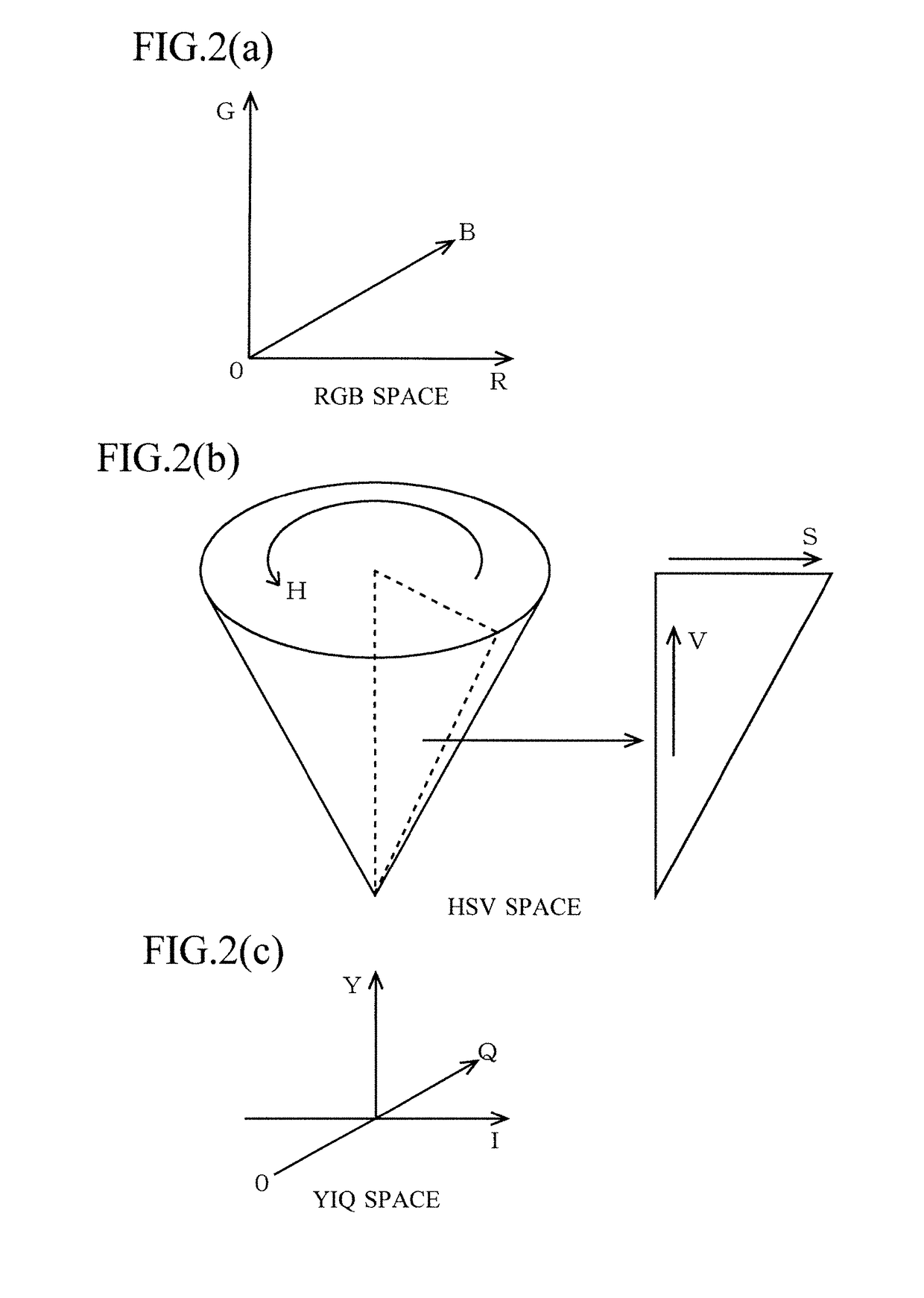
[0293]In this embodiment, since the pulse wave is detected by the color component, it is affected by the fluctuation in chrominance (color quality) characteristics.

[0294]FIG. 12 are a view for explaining the fluctuation in chrominance by the camera characteristics.

[0295]FIG. 12(a) is a view illustrating the fluctuation in the chrominance characteristics of the pixel in the camera 8 by contrast.

[0296]Since the chrominance characteristics are not uniform as above, if the user moves in the screen, a value of the chrominance is changed, which affects accuracy of pulse wave detection.

[0297]FIG. 12(b) is a view illustrating comparison of the detected pulse waves in a left region 61, a center region 62, and a right region 63 in the screen b...


PUM


Abstract

A pulse wave detection device color converts a frame image of a moving image from RBG to HSV components, and identifies a skin section using the skin color of a user prepared in advance with an H component. The device converts the skin section of the image to YIQ components, and takes Qm as a pulse wave signal, Qm being obtained by averaging the Q values of the pixels. The device then obtains a chronological change in the pulse wave signal Qm and outputs the change as a pulse wave. Accordingly, it is possible to exclude disturbance factors from the pulse wave detection target, and successfully detect a pulse wave. The identification of the skin section is performed using the H component to identify candidate pixels, and using the S component to narrow down the candidate pixels to the target, so high-precision identification of the skin section is possible.

Description

TECHNICAL FIELD[0001]The present invention relates to a pulse wave detection device and a pulse wave detection program and relates to those detecting a pulse wave by using image processing, for example.BACKGROUND ART[0002]Detection of a pulse wave is extremely important in understanding a physiological state of a human being and a technology for detecting this from a remote place in a non-contact manner is in demand.[0003]Such technologies include a study made by Massachusetts Institute of Technology which is a non-patent literature.[0004]This technology detects a pulse wave by taking a moving image of the face of a subject by a web camera and analyzing the moving image by a laptop computer after the photographing (that is, not by real-time processing but by processing later).[0005]This study realizes non-contact detection of a pulse wave by using an inexpensive general purpose device and a simple method against conventional detection of the pulse wave by using a special expensive d...

Claims


Application Information

Patent Timeline
Patent Type & Authority Applications(United States)
IPC IPC(8): G06K9/00A61B5/1171G06T5/50G06T7/11G06T7/136A61B5/00
CPCG06K9/00268A61B5/1176G06T5/50G06T7/11G06T7/136A61B5/0013G06T2207/30088G06T2207/10024G06T2207/10016G06T7/0016G06T2207/30076G06T7/90A61B5/14552A61B5/7203A61B5/02G06T1/00A61B5/0245A61B5/00G06T7/00G06V40/168
Inventor JONES, MICHAELYAMADA, HIDEO
Owner EQUOS RES
Why Eureka
Try Eureka