Fluorescence detection device

Active Publication Date: 2018-03-15
DELTA ELECTRONICS INTL SINGAPORE
View PDF2 Cites 5 Cited by
  • Summary
  • Abstract
  • Description
  • Claims
  • Application Information

AI Technical Summary

Benefits of technology

[0007]An object of the present invention is to provide a fluorescence detection device with high signal-to-noise ratio for minimizi

Problems solved by technology

However, the difficulties of developing a fluorescent detection device for portable qPCR system hav

Method used


Image

  • Fluorescence detection device
  • Fluorescence detection device
  • Fluorescence detection device

Examples


Embodiment Construction

[0050]The present invention will now be described more specifically with reference to the following embodiments. It is to be noted that the following descriptions of preferred embodiments of this invention are presented herein for purpose of illustration and description only; it is not intended to be exhaustive or to be limited to the precise form disclosed.

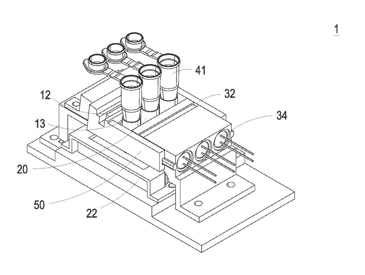
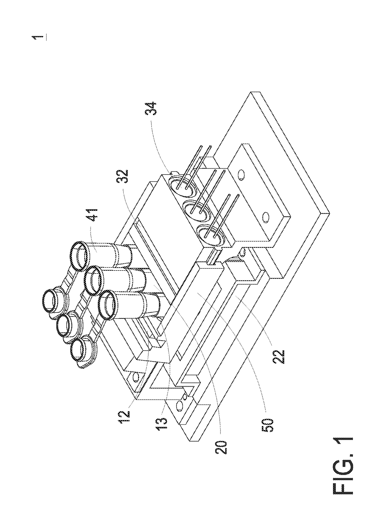
[0051]The present invention provides a fluorescence detection device which is an optical module sequentially illuminating multiple fluorescent samples arranged in linear position. During the qPCR amplification process, the fluorescence detection device provides a single light source to excite fluorescent probes in the nucleic acid sample, and sequentially detects specific fluorescent signals emitted from the probes.

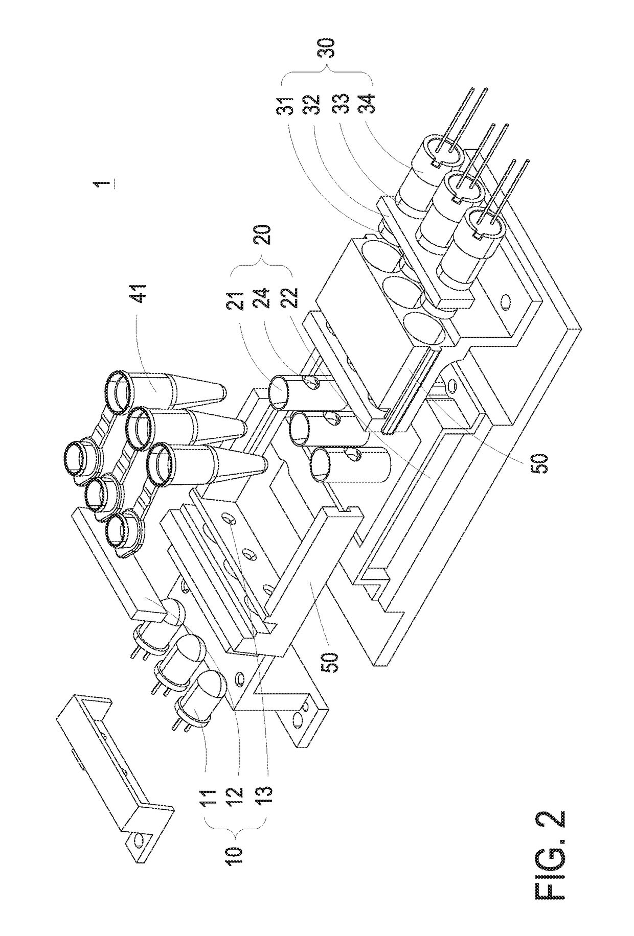
[0052]Please refer to FIGS. 1 to 4, wherein FIG. 1 shows a schematic view of the fluorescence detection device according to a preferred embodiment of the present invention, FIGS. 2 to 3 show exploded views of the fluor...


PUM

PropertyMeasurementUnit
Timeaaaaaaaaaa
Angleaaaaaaaaaa
Angleaaaaaaaaaa

Abstract

The fluorescence detection device includes an illumination module and a detection module. The illumination module includes a light source and a first filter. The light source is configured with the first filter to pass a first light beam at a first particular bandwidth along a first optical axis for exciting a targeted fluorescent probe and generating a fluorescent light. The detection module includes a second filter and a photo-detector. The second filter receives the fluorescent light and passes a second light beam at a second particular bandwidth along a second optical axis. The photo-detector receives the second light beam at the second particular bandwidth and converts the second light beam at the second particular bandwidth to an electrical signal. The first optical axis is tilted from the second optical axis at a specific angle ranged from 4.5 degrees to 9.5 degrees.

Description

CROSS-REFERENCE TO RELATED APPLICATION[0001]This application claims the benefit of U.S. Provisional Application Ser. No. 62 / 393,275 filed on Sep. 12, 2016, and claims the priority to Singapore Patent Application No. 10201704313T filed on May 26, 2017, the entire contents of which are incorporated herein by reference for all purposes.FIELD OF THE INVENTION[0002]The present invention relates to a fluorescence detection device, and more particularly to a fluorescence detection device with high signal-to-noise ratio.BACKGROUND OF THE INVENTION[0003]The demand of acquiring large amounts of a specific segment of DNA efficiently for different purposes is booming in recent years. Among the entire existing DNA sequencing techniques, Polymerase Chain Reactions (PCR) is one of the most economical and straightforward techniques amplifying billion copies of targeted DNA segments in short period of time. The applications of PCR technique are broadly adopted, such as selective DNA isolation for ge...

Claims


Application Information

Patent Timeline
IPC IPC(8): C12Q1/68G01N21/64B01L7/00
CPCC12Q1/686G01N21/6428B01L2300/1822G01N2021/6439B01L2300/0654B01L7/52C12Q1/6851G01N21/64G01N21/6402G01N33/5308G01N33/533G01N2021/6417C12Q2531/113C12Q2563/107G01N21/645G01N2021/6463
Inventor MA, BOHSU, WEI-CHENYIU, JEI-YIN
Owner DELTA ELECTRONICS INTL SINGAPORE
Why Eureka
Try Eureka