Method for producing electrodes having an improved current collector structure

a current collector and electrode technology, applied in the direction of cell components, cell component details, electrochemical generators, etc., can solve the problems of non-homogenous current flow in the electrode, the current produced incrementally on the surface of the electrode is difficult to flow, and the current conducting is associated with losses, so as to improve the ratio of active material to current collector material, improve the effect of current collector structure and significant reduction of portion of current collector material

Active Publication Date: 2018-03-15
ROBERT BOSCH GMBH
View PDF1 Cites 5 Cited by
  • Summary
  • Abstract
  • Description
  • Claims
  • Application Information

AI Technical Summary

Benefits of technology

[0017]Surprisingly, it has turned out that through the provision of such a structural element the danger of a local or zonal overheating of the battery can be significantly reduced or even avoided, and that an electrode having such a structuring can easily be produced starting from a free-standing active material foil. Through the proposed method, the material quantity of the current collector can be matched individually to the particular conditions and requirements of the electrode, and thus the material quantity can be reduced overall.
[0039]A further advantage is the possibility of using current collector layers having low conductivity or thickness. In conventional current collector layers, the thickness of the layer has to be selected such that already before the arrester that is to be connected, the thickness of the layer is adequately such that the current will not be unnecessarily limited. The same quantity of current occurs in each surface region of the electrode. However, the arrester is provided only in a particular region of the electrode, so that in the vicinity of the arrester the current collector layer also has to transport the current quantities occurring in the surface regions situated further away from the arrester. When there is a theoretical halving of the electrode surface, the surface half that bears the arrester then has to have twice the thickness of the second surface half in order to ensure adequate current transport. The method described here makes it possible to adapt the thickness of the current collector layer to the current quantities occurring in the respective region of the electrode, and in this way to optimize the ratio of current collector material to active material.

Problems solved by technology

During the charging and discharging of such a battery, there is now the difficulty that the current produced incrementally in the surface of the electrode flows from all regions of the electrode in the direction of the current collector.
Frequently, the current conducting is associated with losses that appear as a local heating of the battery.
In particular, disturbance points in the ideal configuration, such as non-uniform coating, excessively large particles in the layer, non-homogenous pressing on of the electrodes, or the like, additionally cause a non-homogenous current flow in the electrode.
This can therefore result in an overheating of the battery, locally or zonally, which can cause premature aging, loss of capacitance, or thermal damage to the battery.
From the point of view of the performance of the electrode, however, a realization that is as thin as possible of the current collector is desirable, because this collector does not make any contribution to the actual energy storage.
Instead, the current collector increases the volume and the weight of the battery, and thus reduces the achievable energy density of the battery.

Method used


Image

  • Method for producing electrodes having an improved current collector structure
  • Method for producing electrodes having an improved current collector structure
  • Method for producing electrodes having an improved current collector structure

Examples


Embodiment Construction

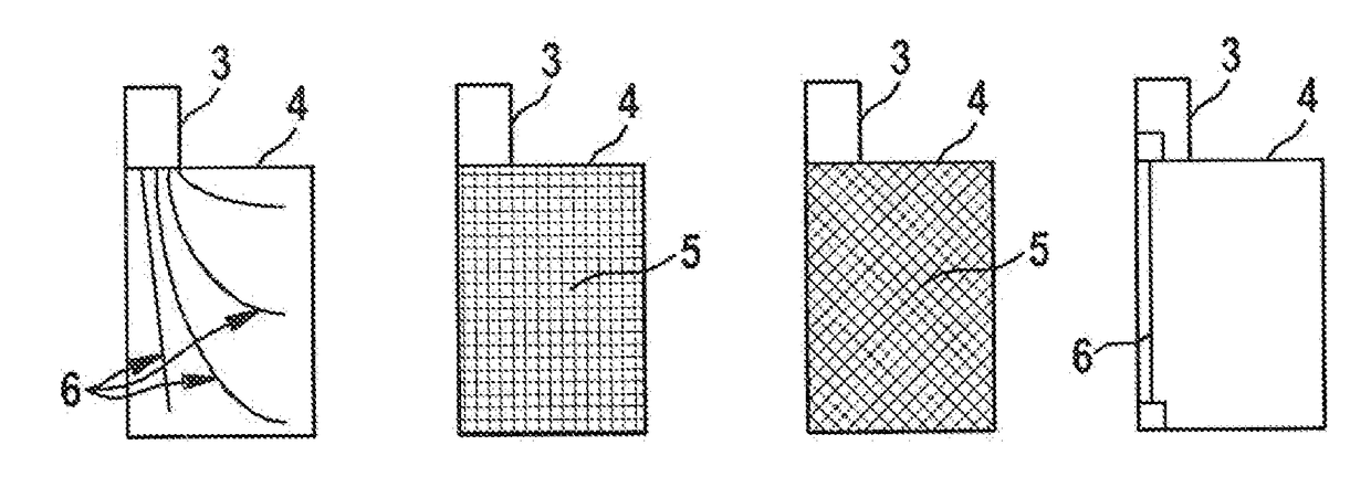
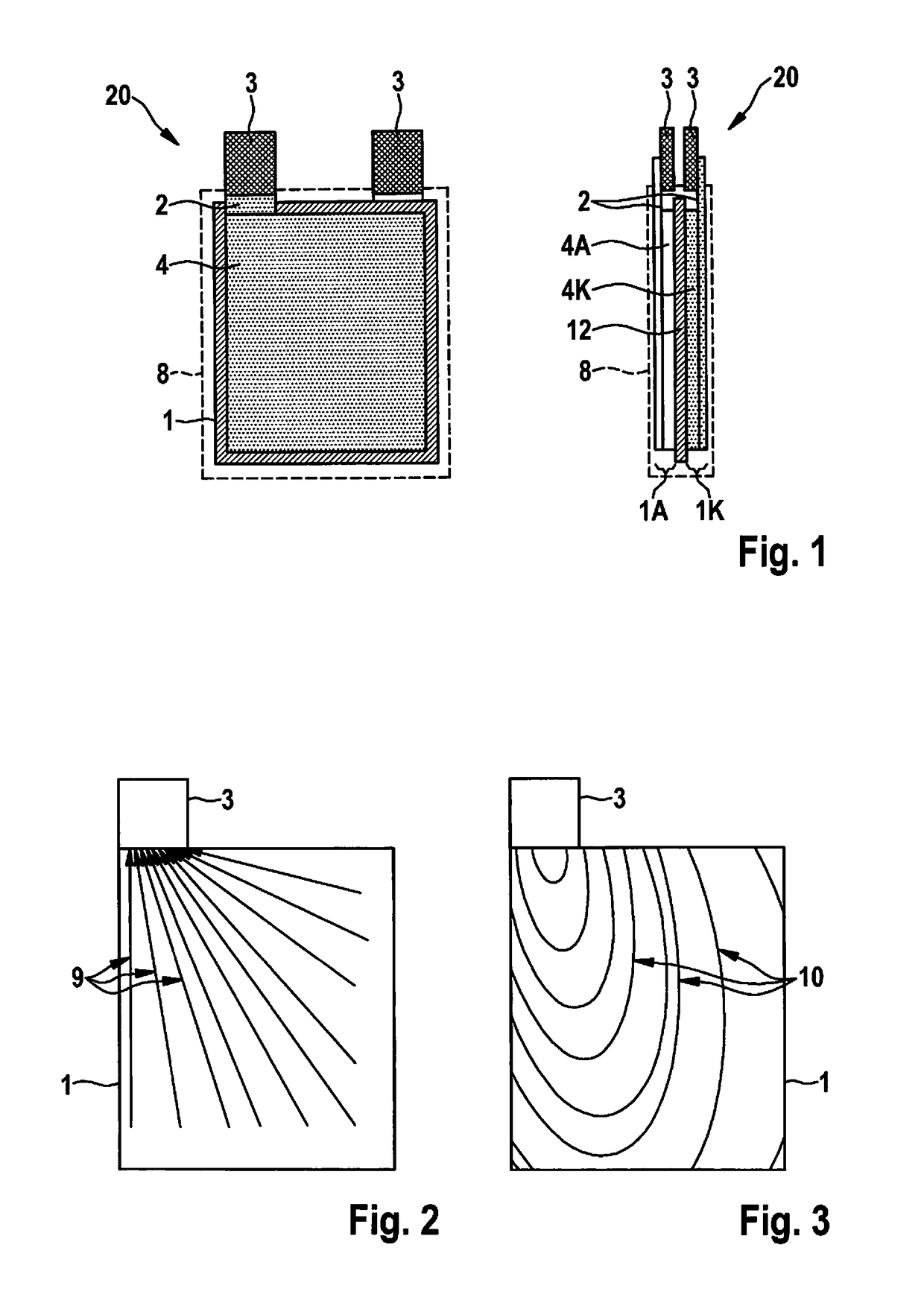
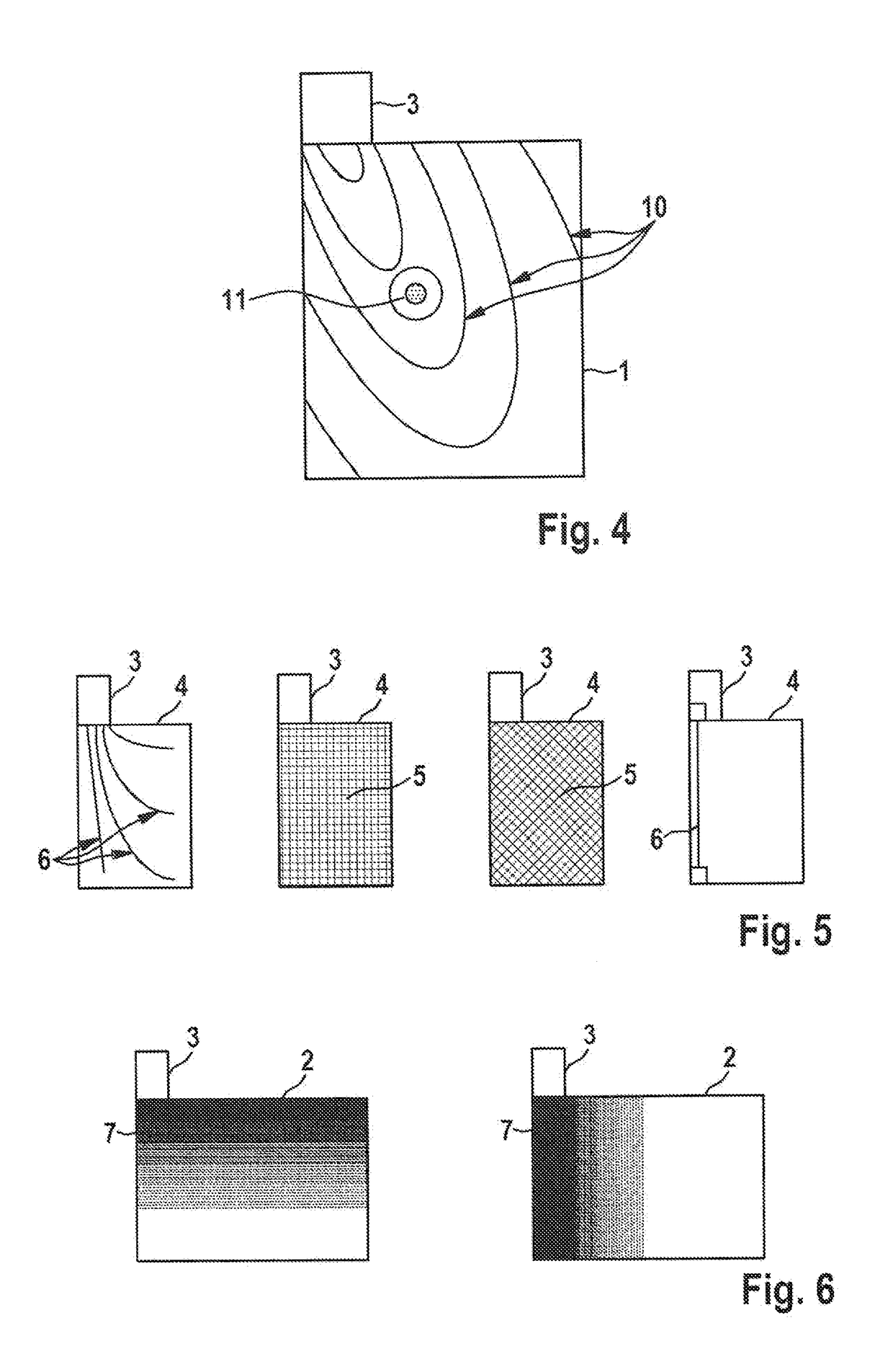
[0047]FIG. 1 shows the general configuration of an electrochemical cell 20. Electrochemical cell 20 is made up of an anode 1A and a cathode 1K, separated from one another by a separator 12. Separator 12 is electrically insulating, but is transparent for ions. Suitable materials for use as separators 12 include for example microporous plastics, glass fiber nonwovens, or polyethylene nonwovens. Cathode 1K and anode 1A are each made of at least one free-standing active material foil 4, in particular an anode active material foil 4A or a cathode active material foil 4K, and a current collector layer 2 applied thereon. Current collector layer 2 can be made for example of copper, nickel, or aluminum, and can be applied onto active material foil 4 using a galvanic method or a pressure method. As cathode material, for example lithium mixed oxides such as Li4Ti5O12, LiCoO2, LiNiO2, LiMn2O4, or lithium iron phosphate (LiFePO4), can be used. As anode material, for example pastes containing gra...


PUM

PropertyMeasurementUnit
thicknessaaaaaaaaaa
thicknessaaaaaaaaaa
thicknessaaaaaaaaaa

Abstract

A method for producing an electrode having an electrically conductive current collector layer having a terminal region for connection to an electrical power circuit, in which to improve the electrical discharge via the terminal region, the current collector layer has at least one structural element having an electrical conductivity that is increased compared to the current collector layer, through which structural element the electrical resistance between a point on the current collector layer and the terminal region is reduced, the method including: providing at least one free-standing active material foil; providing an electrically conductive layer on at least one surface of the active material foil, the electrically conductive layer being formed immediately on the surface of the active material foil to form the current collector layer; and connecting an electrical terminal region to the electrically conductive layer to enable connection to an electrical power circuit.

Description

RELATED APPLICATION INFORMATION[0001]The present application claims priority to and the benefit of German patent application no. 10 2016 217 383.9, which was filed in Germany on Sep. 13, 2016, the disclosure of which is incorporated herein by reference.FIELD OF THE INVENTION[0002]The present invention relates to methods for producing electrodes having improved current collector structures for conducting away electrical energy in batteries, such as a lithium-ion battery. In particular, the present invention relates to a method in which the current collector structure is applied onto a free-standing active material foil.BACKGROUND INFORMATION[0003]For the production of batteries, such as lithium-ion batteries, standardly an active material layer is applied onto an electrically conductive current collector. As an active material layer, for example pastes containing graphite or nanocrystalline amorphous silicon having lithium deposits, or also pastes including mixed oxides containing li...

Claims


Application Information

Patent Timeline
Patent Type & Authority Applications(United States)
IPC IPC(8): H01M4/72H01M4/66H01M2/30H01M2/26H01M50/55H01M50/553
CPCH01M4/72H01M2/26H01M2/30H01M4/662H01M4/04H01M4/13H01M4/661H01M4/70H01M4/88H01M8/0202H01M8/0206H01M50/553H01M50/55H01M4/139H01M8/0247Y02E60/50Y02E60/10
Inventor BAUER, HARALD
Owner ROBERT BOSCH GMBH
Why Eureka
Try Eureka