Dc-dc converter device

a converter device and dcdc technology, applied in the direction of electronic device motherboards, process and machine control, instruments, etc., can solve the problems of reducing the size of a typical transformer, affecting the operation of the converter device, so as to reduce the loss, reduce the loss, and reduce the input power

Active Publication Date: 2018-03-15
MURATA MFG CO LTD
View PDF6 Cites 8 Cited by
  • Summary
  • Abstract
  • Description
  • Claims
  • Application Information

AI Technical Summary

Benefits of technology

[0009]Preferred embodiments of the present invention provide miniaturized DC-DC converter devices that require less input p

Problems solved by technology

This is desirable because typically the space available for mounting the converter device onto a PCB, for example, a motherboard of an electronic device, will be very limited.
There are, however, practical limitations on the size to which a typical transformer can be reduced.
Reducing the size of the transformer's magnetic core, for example, results in the core becoming saturated more quickly, lead

Method used


Image

  • Dc-dc converter device
  • Dc-dc converter device
  • Dc-dc converter device

Examples


Embodiment Construction

[0024]Hereinafter, the present invention will be clarified through description of specific preferred embodiments of the present invention with reference to the drawings.

[0025]It is to be noted that the preferred embodiments described in this specification are merely examples, and that the configurations in the preferred embodiments are able to be partly replaced or combined between different preferred embodiments.

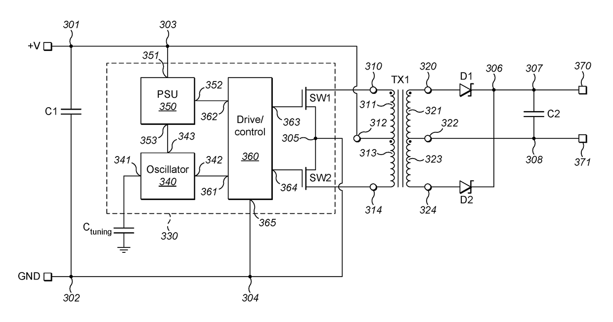
[0026]Preferred embodiments of the present invention include an embedded converter device with first and second transformer windings disposed around a magnetic core embedded in a substrate. The converter device may be used as a portion of switching power electronic devices, for example. The device is described with respect to preferred embodiments of the present invention shown in FIGS. 2 to 4, which will be discussed in detail below.

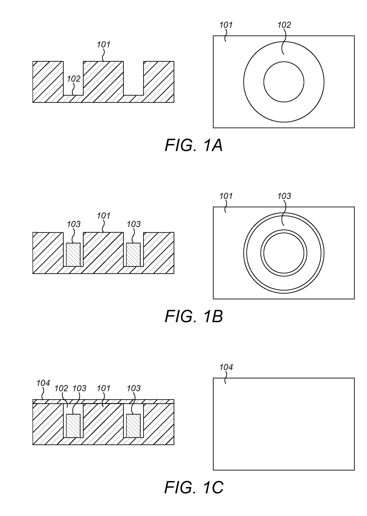
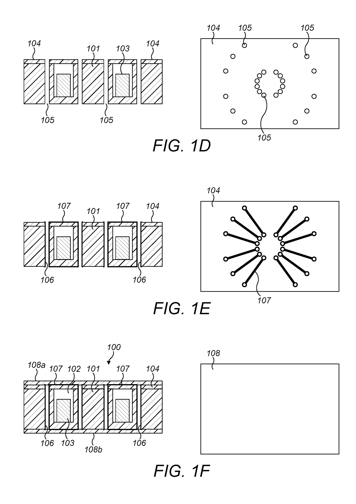
[0027]For ease of understanding, an example of a method of manufacturing a converter device will now be described with reference to FIGS. 1A t...


PUM


Abstract

A DC-DC converter includes an insulating substrate; a magnetic core embedded in the insulating substrate, the magnetic core having non-zero x, y and z dimensions of less than or equal to about 5.4 mm by about 5.4 mm by about 1.8 mm; separate primary and secondary transformer windings surrounding first and second regions of the magnetic core; and a control circuit including: an oscillator; a drive circuit coupled to the oscillator; and one or more switches coupled to the drive circuit; the drive circuit providing a switching signal to the one or more switches and energizing the one or more switches to provide a drive voltage to the primary transformer winding. The one or more switches are Field Effect Transistors implemented in a Silicon-on-Insulator configuration or as a Silicon-on-Sapphire configuration.

Description

CROSS REFERENCE TO RELATED APPLICATIONS[0001]This application claims the benefit of priority to British Patent Application GB1615743.0 filed on Sep. 15, 2016, and the entire contents of this application are hereby incorporated herein by reference.BACKGROUND OF THE INVENTION1. Field of the Invention[0002]The present invention relates to an embedded DC-DC converter device, and in particular to a DC-DC converter device with improved power efficiency.2. Description of the Related Art[0003]It is known, for example in U.S. 2011 / 0108317 A1, to provide low profile transformers and inductors in which the magnetic components are embedded in a cavity in a resin substrate, and the necessary input and output electrical connections for the transformer or inductor are formed on the substrate surface. A printed circuit board (PCB) for a power supply device can then be formed by adding layers of solder resist and copper plating to the top and / or bottom surfaces of the substrate. The necessary electr...

Claims


Application Information

Patent Timeline
IPC IPC(8): H02M1/08H02M3/337H01F27/24H01F27/28H05K1/18H05K1/11
CPCH02M1/08H02M3/3376H01F27/24H01F27/28H05K1/181H05K1/115H02M2001/0048H05K2201/1003H01F27/2804H01F27/2895H01F27/324H02M3/33573H02M3/337H02M1/40H05K1/165H05K2201/086H01F2027/2809H01F2027/2819Y02B70/10H01L27/1203H02M7/003H02M1/0048
Inventor KNELLER, QUINNPARISH, SCOTTMOFFAT, MARK
Owner MURATA MFG CO LTD
Why Eureka
Try Eureka