
Automated device for drilling a hole in the vault and walls of a tunnel and for installing an anchoring element into said hole

a technology of tunnel vault and vault walls, which is applied in the direction of gripping heads, work benches, arms, etc., can solve the problems of operator unsatisfactory intervention, unsatisfactory drilling of each hole and installation of each respective anchoring element, and operator exposure to conditions harmful to his health

Active Publication Date: 2018-03-22
BOUYGUES TRAVAUX PUBLICS SA
View PDF2 Cites 10 Cited by
  • Summary
  • Abstract
  • Description
  • Claims
  • Application Information

AI Technical Summary

Benefits of technology

The patent describes a device that reduces the risk of falls and danger to operators by using a robotic arm to drill holes in inaccessible zones. This device also prevents exposure to harmful conditions, improves accuracy and repeatability, and increases productivity by operating for several hours at a high rate.

Problems solved by technology

This intervention by an operator proves unsatisfactory for various reasons.
On the one hand, the drilling of each hole and the installation of each respective anchoring element require considerable time.
On the other hand, the operator is exposed to conditions harmful to his health, such as an atmosphere loaded with dust, a noisy environment, without counting the risks associated with working at a height.
However, drilling holes into the vault of a tunnel has a greater complexity than into the ground, and imposes in particular controlling the position and orientation of the robot in the three spatial directions.
On the other hand, document [1] does not address the problem of automated installation of anchoring elements in the holes.
This document does not address the problem of precise positioning of the hole in the vault of a tunnel already constructed, nor that of installing anchoring elements.

Method used


Image

  • Automated device for drilling a hole in the vault and walls of a tunnel and for installing an anchoring element into said hole
  • Automated device for drilling a hole in the vault and walls of a tunnel and for installing an anchoring element into said hole
  • Automated device for drilling a hole in the vault and walls of a tunnel and for installing an anchoring element into said hole

Examples


Embodiment Construction

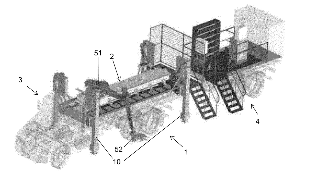
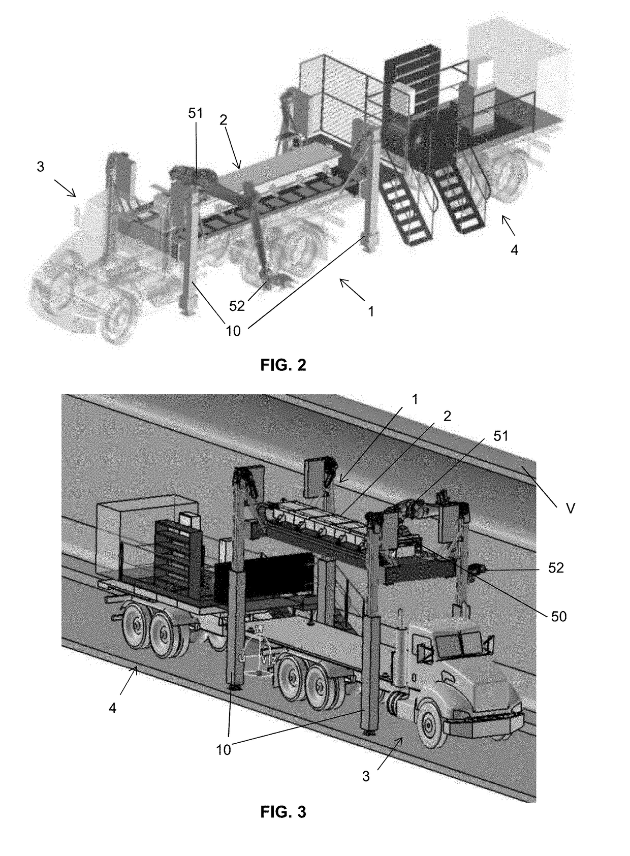
[0047]Generally, the device according to the invention comprises a robot having a base, a robotic arm articulated with six degrees of freedom extending from the base, and a multifunctional head arranged at the end of the arm and movable over 360 degrees. The base is mounted on a device for guiding in translation, itself attached to an elevating platform the height whereof is adjustable to allow the multifunctional head to reach the desired position on the vault or the walls of the tunnel.

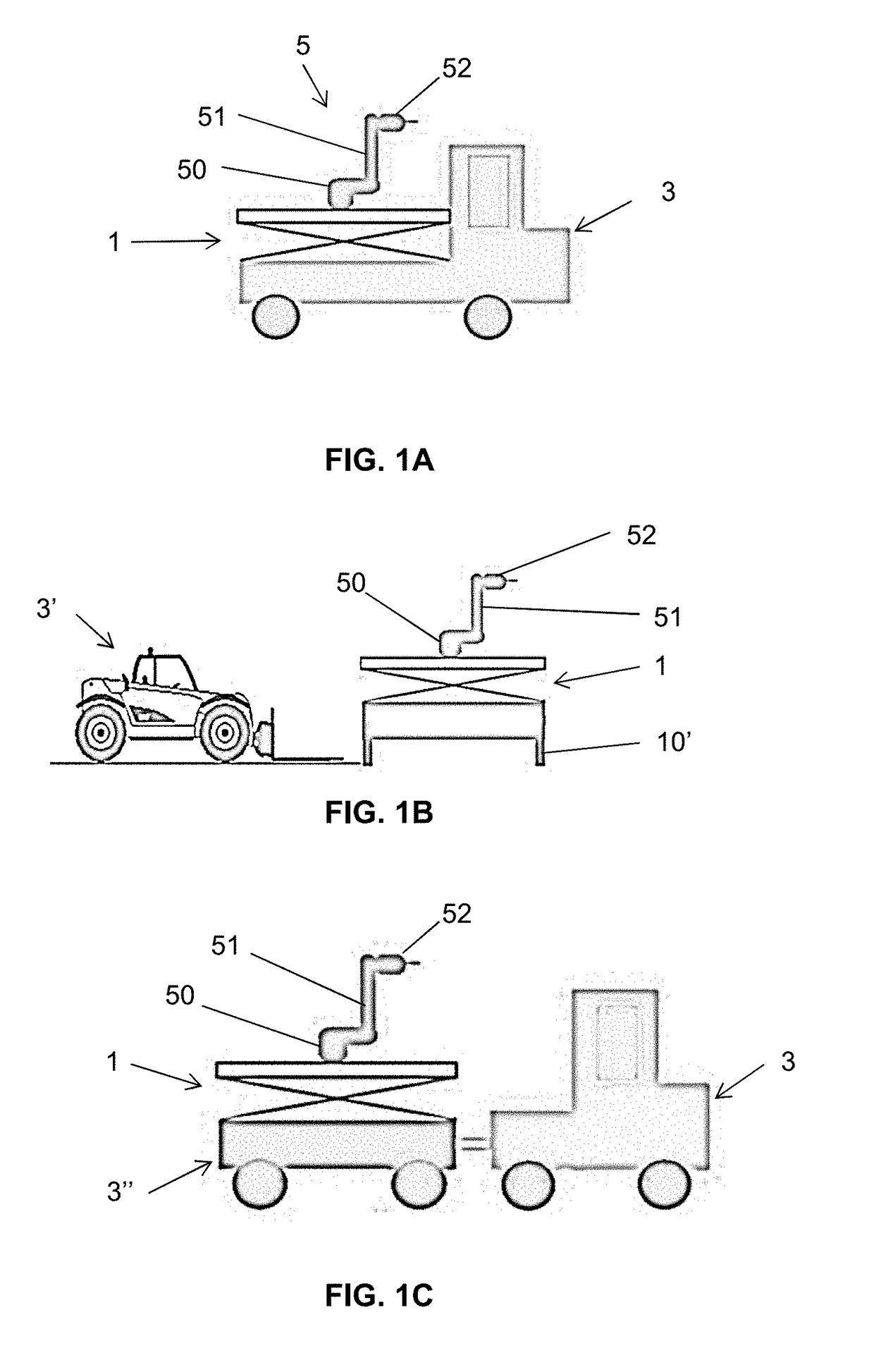
[0048]FIGS. 1A to 1C illustrate different non-limiting modalities of transportation of the device inside the tunnel.

[0049]With reference to FIG. 1A, the platform 1 is carried on the bed of a truck. The robot is designated by the symbol 3, the device for guiding in translation not being shown in FIGS. 1A to 1C. The truck is provided with stabilizers (not shown) ensuring the stability of the device when the robot is operating.

[0050]In the embodiment illustrated in FIG. 1B, the platform 1 is autonomous...


PUM

PropertyMeasurementUnit
Angleaaaaaaaaaa
Heightaaaaaaaaaa

Abstract

The invention relates to an automated device for drilling a hole in the vault and walls of a tunnel and for installing an anchoring element in said hole, characterized in that it comprises:a robot (5) comprising a base (50), a robotic arm (51) extending from the base and a multifunctional head (52) arranged at the end of the arm and movable over 360 degrees, said multifunctional head comprising a drilling means (520), a percussion means (521) suitable for inserting an anchoring element in the hole, and a vision system (522),an elevating platform (1) bearing a device (2) for guiding in translation the base of the robot,a control unit suitable for communicating with a controller of the robot and comprising a processor configured to determine in real time the position of the robot in a three-dimensional reference frame of the tunnel and a man-machine interface.

Description

FIELD OF THE INVENTION[0001]The present invention relates to an automated device for drilling a hole in the vault and walls of a tunnel and for installing an anchoring element into said hole.BACKGROUND OF THE INVENTION[0002]During the construction of a tunnel it is necessary to attach objects, such as cables, pipes, lighting, traffic signs, etc. to the vault of the tunnel, the surface whereof is generally made of concrete.[0003]A tunnel several kilometers in length can thus require the drilling of several tens of thousands of holes in the vault and walls.[0004]To this end, it is necessary to drill a hole in the vault or wall of the tunnel, and then to insert into it an anchoring element, such as a dowel, allowing the attachment of the object.[0005]At the present time, these operations are carried out by an operator.[0006]Considering the height of the vault (several meters), it is necessary to install a scaffolding so that the operator can be in a suitable position with respect to th...

Claims


Application Information

Patent Timeline
IPC IPC(8): E21D20/00E21B7/02E21B19/087E21D9/13
CPCE21D20/003E21B7/025E21B19/087E21D9/13E21B7/022B25J18/04B25H1/0035B28D1/146B25J5/06B25J11/00B25J15/0066B28D1/14E21F17/02E21D9/106E21D9/1093
Inventor FURGE, JEROME
Owner BOUYGUES TRAVAUX PUBLICS SA
Learn More