Mobile devices for tracking a radiation disk light source and methods using same

a technology of radiation disk and light source, applied in direction finders, direction/deviation determining electromagnetic systems, instruments, etc., can solve problems such as logistical challenges, and achieve the effect of optimizing the tracking precision of light sour

Active Publication Date: 2018-03-29
UNIV OF COLORADO THE REGENTS OF
View PDF0 Cites 10 Cited by
  • Summary
  • Abstract
  • Description
  • Claims
  • Application Information

AI Technical Summary

Benefits of technology

[0012]In certain embodiments, the method comprises recording and evaluating incoming radiation disk images to determine the relative center positions of the aperture and the incoming radiation disk, in order to determine if the incoming radiation focused onto the front side of the aperture plate is within the imaging device's field of view. In other embodiments, a threshold is applied to convert incoming radiation disk images to binary format contours. In yet other embodiments, the incoming radiation disk images are distinguished from the aperture plate and aperture which are not exposed to the incoming radiation. In yet other embodiments, the binary format contours are subjected to an ellipse- or circle-fitting algorithm. In yet other embodiments, the position of the fitted ellipse or circle center is determined relative to the aperture. In yet other embodiments, the position of the fitted ellipse or circle center relative to the aperture is corrected for any motion observed between measurements. In yet other embodiments, the relative position of the fitted ellipse or circle center is used to optimize the light source tracking precision.

Problems solved by technology

However, logistical challenges arise when measurements observe the direct solar beam from a moving platform, e.g., due to highly uncorrelated motions of vehicles on roads.

Method used


Image

  • Mobile devices for tracking a radiation disk light source and methods using same
  • Mobile devices for tracking a radiation disk light source and methods using same
  • Mobile devices for tracking a radiation disk light source and methods using same

Examples


example 1

le Based Mobile Solar Tracker

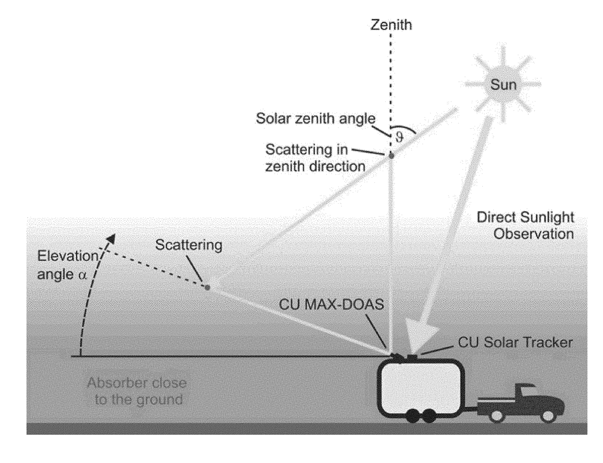
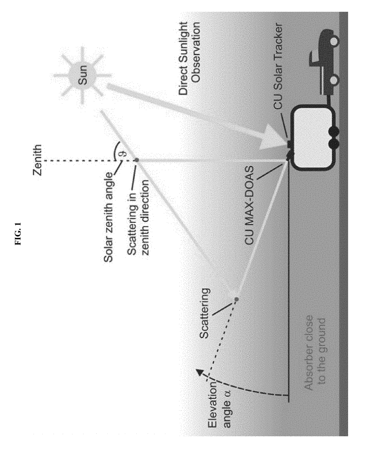
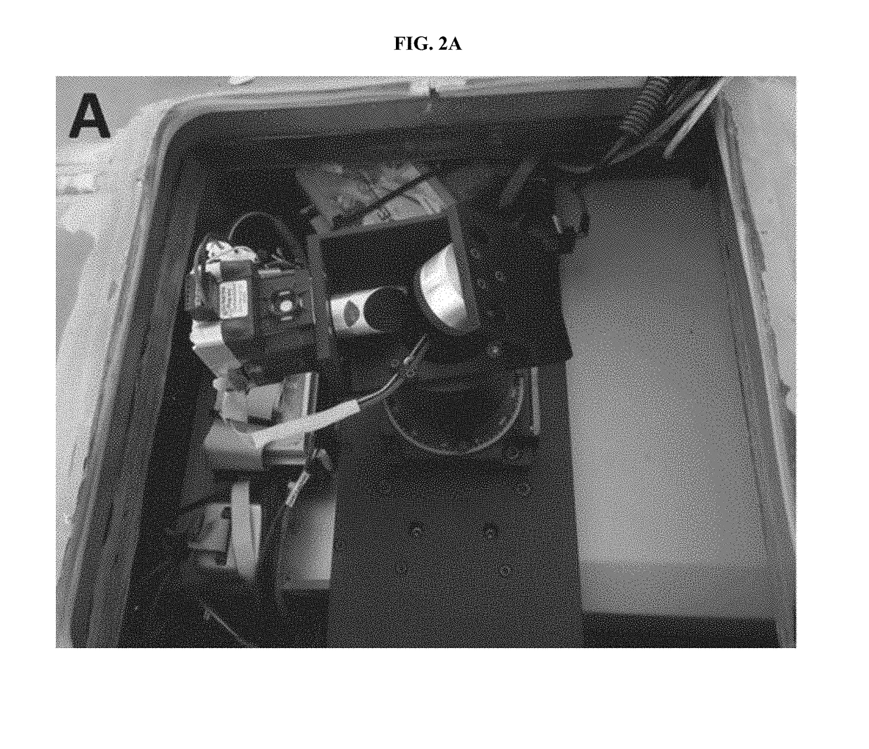
[0068]The mobile solar tracker as deployed aboard the mobile laboratory (FIG. 1) is shown in FIGS. 2A-2B in a top-down and side view. The solar tracker is an alt-azimuthal tracker consisting of two mirrors. The first mirror is mounted at a 45° angle directly on a stepper motor and allows access to any EA. The direct coupling of the mirror permits fast backlash free movements. The second mirror is mounted at a 45° angle opposite to the first mirror. The two mirrors are mounted on a rotational stage that is driven by a second stepper motor. The electrical connection is realized via a slip ring that transmits communication and power to the EA motor and permits unrestrained and continuous 360° rotation of the mirror system. The rotational stage and the slip ring have inner (hollow axle) diameters of 2 and 1.5 inches, respectively, that transmits the solar beam. FIGS. 2C and 2D show optical schematics of exemplary embodiments of the solar tracker. The light i...

example 2

Algorithm

[0071]The operation of the mobile solar tracker is based on a two-level algorithm as shown in FIG. 3. First, the real-time pitch, roll, and heading information of the platform is used as Euler angles to correct the astronomical solar position and locate the sun in the sky relative to the vehicle orientation. This calculated sun position in the local vehicular coordinate system provides the coarse mirror angles to the motors to bring the solar disk into the FOV of the camera. The solar disk images are recorded and evaluated to determine the center position of the aperture and the solar disk. First, a threshold is applied to convert the image to binary format to distinguish the bright solar disk from the dark aperture plate and aperture. Next, an ellipse fitting algorithm is applied to the binary image contours. For subsequent images, depending on the distance of the solar disk to the aperture, either a circle or an ellipse fitting algorithm is applied. The circle and ellipse...

example 3

d Motion Compensation System and Imaging Feedback

[0074]The primary function of the motion compensation system in the mobile solar tracker setup is to accurately determine the real-time orientation of the platform in order to locate the sun in the sky while moving. The secondary purpose is to make a small correction in the imaging data in order to account for the lag time it takes to record the camera image of the solar disk, process it, and update the new motor target position. The given angle accuracy by the manufacturer for the pitch, roll, and heading from the MMQ-G is 0.29°. In practice, the pitch angle measured by the MMQ-G and an independent angle sensor on the NSF / NCAR GV research aircraft agree within 0.15° (1σ). However, the angular diameter of the solar disk is 0.53° in the sky, and the motion compensation system by itself is not good enough to track the sun accurately while moving. The imaging setup is needed for very high tracking precision. However, with the uneven moti...


PUM


Abstract

The invention provides in one aspect a fast digital light source tracker aboard a moving ground-based or airborne platform. The tracker consists of two rotating mirrors, a lens, an imaging camera, and a motion compensation system that provides the Euler angles of the mobile platform in real time. The tracker can be simultaneously coupled to UV-Vis and FTIR spectrometers, making it a versatile tool to measure the absorption of trace gases using the light source's incoming radiation.

Description

CROSS-REFERENCE TO RELATED APPLICATIONS[0001]This application claims the benefit of priority under 35 U.S.C. § 119(e) of U.S. Provisional Patent Application No. 62 / 398,852, filed Sep. 23, 2016, the entire disclosure of which is hereby incorporated herein by reference.BACKGROUND OF THE INVENTION[0002]Mobile column measurements provide a means to characterize the distribution of trace gases over a large spatial scale while capturing the atmospheric variability over the column. Combined with wind measurements, mobile column measurements of trace gases have been shown to be very useful to constrain emission of trace gases from source regions by applying a mass conservation approach. Mobile column measurements from various platforms have previously been used to estimate: nitrogen oxides (NOx) emissions from cities; nitrogen dioxide (NO2), sulfur dioxide (SO2), and formaldehyde (HCHO) emissions from industries using the differential optical absorption spectroscopy (DOAS) technique; and fu...

Claims


Application Information

Patent Timeline
Patent Type & Authority Applications(United States)
IPC IPC(8): G01S3/786G01S3/781G01S3/783G01S3/789
CPCG01S3/7862G01S3/781G01S3/783G01S3/789G01N21/31G01N2021/3531G01N2021/3595
Inventor VOLKAMER, RAINERBAIDAR, SUNILTHOMSON, DAVID
Owner UNIV OF COLORADO THE REGENTS OF
Why Eureka
Try Eureka